I want to build a small POV display, but how is the power (and if possible a communication line) transmitted to the spinning part?
I've looked at some POV project, but they usually don't explain that part much...
I want to build a small POV display, but how is the power (and if possible a communication line) transmitted to the spinning part?
I've looked at some POV project, but they usually don't explain that part much...
You need to use some form of slip ring and carbon brushes. The slip rings are mounted on the spinning shaft which is a ring of brass that makes contact with sprung brushes that supply the power. They are similar to a commutator on a DC motor, except they are a continuous ring instead of segmented.
You'll need two slip rings for power and GND unless it's possible to use the shaft itself as GND. In that case, you can get away with just one. But this would mean you'd need to mount all of your control circuitry on the spinning assembly, otherwise you'd also have to have extra rings to supply individual LED circuits.
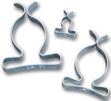
A neat and cheap alternative to using carbon brushes is to use tool clips that are mounted on a piece of insulating nylon that surround the rings.

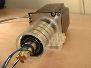
Here's some instructions on building a rather ingenious slip ring using ball bearings.

If you are building a small display, you can also do it with a round circuit board with circular traces that rotates coaxially with your rotating part with two fixed "brushes" (small brass springs) that each drag on one of the circular traces. Like a flattened out version of how a DC motor commutator works.
The slip ring is the most obvious solution, but it's prone to wear and noise. An alternative may be a videohead from an old VCR. They contain coils that act as a transformer to transfer the video signal from the magnetic heads in the rotating part of the head to the fixed part. Very quiet and low wear.
Please check out the list of POV displays. Many POV displays are "open-hardware" and so should have extensive documentation on exactly how their power and communications work -- if one doesn't have enough detail, try another one.
Nearly all POV displays that I've seen working use slip rings for power. (I've seen one working commercial POV display that uses an alternative to slip rings for power, and I plan to build a spinning POV display without slip rings that transfers power in a completely different way, but it's currently highly experimental). Power on the stationary side goes through the slip ring to a large capacitor (to ride out power glitches from bounces and non-conductive dirt in the slip ring) at typically 8 to 12 V, which supplies power to a voltage regulator that powers the microcontroller and the chips that apply power to the LEDs.
Many POV displays have no communication between the stationary part and the spinning part -- any user-interface buttons are on the spinning part, and you have to stop the motion, push the buttons (with a difficult-to-read linear LED array for feedback), then re-start the motion.
Some POV displays have a "communications" slip-ring or two for serial communication between the spinning part and the outside world. Alas, the slip ring adds glitches that are difficult to ignore.
Many POV displays have a Hall effect sensor on the rotor that passes a fixed magnet, so the spinning microcontroller can compensate for the actual rotational speed. In principle, one could send data from a stationary coil to a spinning Hall effect sensor near the rotational axis, but I haven't seen that actually working.
Some of them use infrared communication between the stationary part and the spinning part, much like IrDA or TV remote controls.
I'm surprised to be the first one to mention this, but:
Build a generator! Attach a magnet to the fan casing, and length of copper cable wound in a manner so that the field lines from the the magnet pass through those windings perpendicularly as they pass the magnet, rectify the resulting voltage, and store the energy in a large capacitor for use with a voltage regulator.
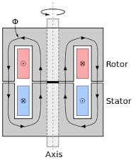
Besides having a lot of "chatter" and there being limited power handling capabilities in the contact another alternative is to use a rotating transformer. The primary and secondary can be used on the stationary vs the rotating platform and transmit energy across an air gap.
One key aspect is to ensure that there is not a lot of "run out" in air-gap as this presents itself as a variable reluctance.
Here is one instance taken from Wikipedia:

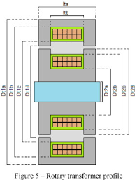
and another taken from here

These can even be used to transmit signals ...
How I've made them in the past is to use pot cores Which are like inside out toroids. Here is a picture from dexter magnetics:

You use two bobbins to wind your primary/secondary on. cast them with epoxy and then mount the two open faces close together.