1
\$\begingroup\$

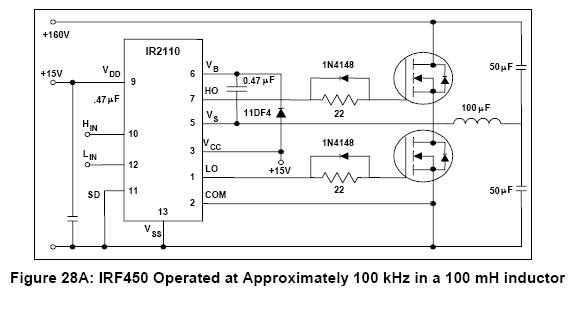
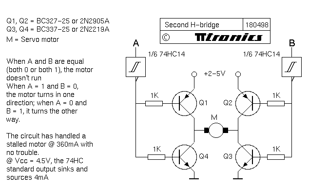
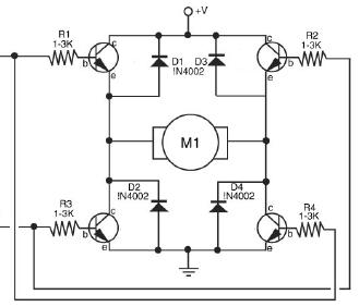
In most of the H-bridge driver circuits I've come across so far, there's a resistor in the path of the signal to the gate/base of the mosfets/BJTs, like in the images below enter image description here enter image description here enter image description here enter image description here
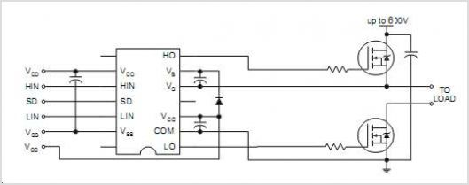
why is it put there ? wouldn't it drop the signal voltage level to somewhat lower value ? Especially in case of power mosfets, the value of instantaneous current flowing into the gate can reach up to 3-4Amps(at high frequencies) and this resistor would dissipate much energy, so would it be okay if I apply signal directly to the gate without putting the resistor? and If it's not possible to get rid of it then what value resistor should I use and upon what factors does its value depend? I'll be using tl494 to generate the signal at about frequency of 50KHz and ir2113 to drive the H-bridge.

\$\endgroup\$

1 Answer 1

10
\$\begingroup\$

The reasons are different depending on if it is a BJT or a MOSFET.

The effect, though, is the same - it's there to reduce current and protect the IO pins on the controller that are driving the transistors.

On the BJT the base -> emitter junction is essentially like a diode, and without a resistor would be like a near short circuit. The resistor stops the transistor drawing too much current from the IO pin.

On the MOSFET the gate is like a capacitor. When you transition from a LOW to a HIGH the capacitor has to charge up. This charging of the capacitor causes a current spike which quickly decays. The resistor is there again to protect the IO pin from this current spike.

The value of the resistor on the BJT is not particularly critical, as long as it allows enough current to flow from the collector to the emitter to drive the load. On the MOSFET, however, selection is more critical, as the resistor, coupled with the capacitance of the gate, creates a low pass filter as the resistor slows down the charging of the capacitor. The resistor must be low enough to allow the MOSFET to switch fast enough for your signals (e.g., PWM) yet high enough for the current to not endanger the IO pin.

\$\endgroup\$
3
  • 1
    \$\begingroup\$ The MOSFET gate resistor is (also) used to limit the switching speed of the MOSFET. (Otherwise ther would never be a gate resistor when a dedicated MOSFET driver is used). Check the second schematic: there is a resistor so slow the ON switching, but a diode over it so the OFF switching is not slowed down. In this case that is probably to prevent 'shoot through' (both MOSFETs conducting at the same time). \$\endgroup\$ Commented Jul 22, 2014 at 19:17
  • \$\begingroup\$ thanks for your answer,, but I've one more question,, sometimes there's a resistor(some call it "pull down resistor") between gate and source,, how does this resistor help? \$\endgroup\$ Commented Jul 23, 2014 at 10:50
  • 1
    \$\begingroup\$ It stops the gate from floating when the input isn't being actively driven by the controller. Most microcontrollers have their IO pins in input mode when the chip powers up, which is basically high impedance, not with any voltage on it. The pull down resistor ensures the gate doesn't pick up random noise and turn itself on, which when you have it attached to a piece of industrial machinery could be lethal. \$\endgroup\$
    – Majenko
    Commented Jul 23, 2014 at 11:46

Your Answer

By clicking “Post Your Answer”, you agree to our terms of service and acknowledge you have read our privacy policy.

Not the answer you're looking for? Browse other questions tagged or ask your own question.