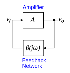
In this answer, I like to add something which explains why and how oscillations at one single frequency are possible:
1.) As an alternative to the "system pole" explanation a "linear" oscillator must fulfill Barkhausen´s oscillation condition (which is a necessary one only):
Loop gain LG=1 (0 dB).
That means: Unity gain magnitude around the feedback loop and a phase of 360 deg (0 deg). Sometimes, a phase shift of 180 deg is mentioned, however, this requirements neglects the minus sign at the summing node - if it exists (example: phase shift oscillator)! However, there are many oscillators (Wien oscillator) which are based on positive feedback - and in this case only the 360 deg rule applies.
2.) However, Barkhausen´s condition (LG=1) applies to the steady state only (continuous oscillation). Of course, due to tolerances and other uncertainties, this condition cannot be fulfilled exactly. For this reason, and to allow a safe start of oscillations the loop gain is designed from the beginning for a value LG>1 (slighly above unity). Hence, a non-linear amplitude stabilization mechanism is necessary which reduces the loop gain for rising amplitudes (in some simple cases it is the limit set by the power supply). The quality of the oscillation signal primarily is determined by this amplitude stabilization method (diodes, AGC-loop,...)
3.) To ensure that this oscillation condition exists at one single frequency only, the loop gain (not only the feedback circuit!) must fulfill Barkhausen´s condition at one single frequency only. However, it is not necessary that the feedback network is frequency-selektive (bandpass).
There are many counter examples (allpass oscillator, phase shift oscillators, integrator based oscillators, GIC resonators,..). Let´s take as a typical example an allpass based oscillator: The magnitude condition is fulfilled for a broad range of frequency - however, the phase condition (zero resp. 360deg) is fulfilled at one single frequency only. The opposite applies to the integrator-based topologies: The phase condition is met for a broad frequency range but the magnitude condition (0 dB) for one frequency only.
4.) As a summary, I like to add one beautiful sentence which describes the problem of designing a good high-quality oscillator: In order to work as a good "linear" oscillator the circuit must contain a certain degree of non-linearity.
EDIT: As to your question: What physical mechanism prevents existence of a second oscillation and makes the first one dominant?
Your question touches the problem of oscillation start, phase noise and frequency uncertainties. I think, the answer requires some detailed explanations:
1.) At first, I think it is proved that thermal noise plays only a minor role during the starting phase. In reality, it is mainly the power switch-on transients of the reactive network which allows safe start of oscillations - if the condition for the loop gain LG>1 is fulfilled for a frequency in the vicinty of the desired oscillation frequency.
2.) Why in the "vicinity"? For LG>1 the system pole is NOT located at the imaginary axis (as in the ideal case) but slightly shiftet into the right half of the s-plane (RHP). This means: During start of the oscillation the frequency is not exactly as expected.
3.) What happens during and after amplitude/gain limitation? For the sake of simplicity let´s assume that we have a kind of AGC (for example: FET- controlled gain determining resistor). Now - for rising amplitudes, the gain is decreased and the system poles are shifted back to the imag. axis and slightly into the LHP before the control action brings the pole back again - and so forth. Result: Only at the very moment when the poles are directly on the imag. axis the frequency of oscillation assumes its designed value.
4.) Hence, this process of gain control causes the oscillation frequency NOT to be constant. Instead the frequency swings to a certain extent around the desired center frequency. At the same time, also the amplitude does not remain constant. This process (breathing of the amplitude) can be easily observed using circuit simulation. The corresponding time constant is determined by the time constant of the rectifying circuit feeding the controller. As a consequence, the signal output of the oscillator can be seen as a frequency (carrier) which is slightly modulated (FM and AM). However, for a well designed oscillator these deviations are within acceptable limits.
5.) Similar (but not the same ) effects can be observed for amplitude limitations caused by anti-parallel diodes. In this case, we face a rather complicated (non-linear) process consisting of limitation, transient generation, filtering and/or phase shifting. As a result, also in this case the frequency of oscillation slighly varies around the designed value.

