-1
\$\begingroup\$

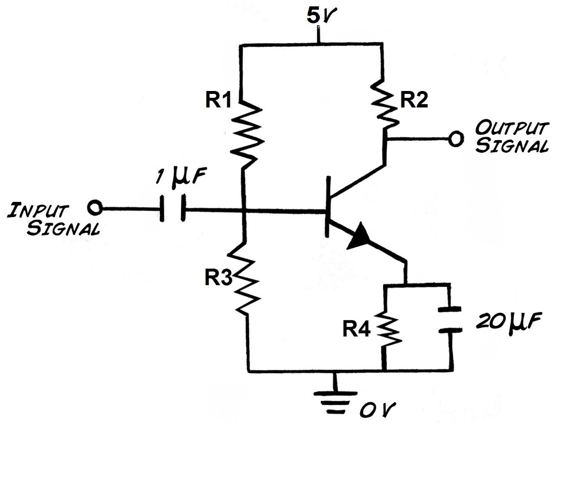
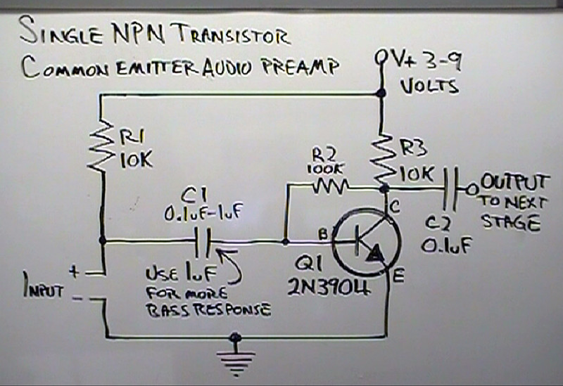
The configuration of the common emitter amplifier is one resistor at the emitter, on resistor at the collector, two bias resistors at the base as shown in this picture :

enter image description here

  1. What is the benefit from this new configuration?
  2. Why is it necessary to change the previous configuration?
  3. What will happen if I used the previous one instead of the new one?
  4. Which one is more useful for RF applications?

enter image description here

\$\endgroup\$
0

3 Answers 3

1
\$\begingroup\$

First, the two schemes presented, showing common emitter configurations. The name of this configuration, because the emitter terminal is shared by the input circuit and the output circuit.
The main difference between the two, is polarization. While the first uses a resistor divider to set the base current at rest, the second uses the resistive circuit, associated to the collector. In principle, by using the resistor divider, can select resistance values ​​that give good bias stability against variations own transistor parameters.

As for the application of both circuits in RF, I think it's more a matter of working with class C amplifiers and tuned output circuits. Perhaps you have generated some confusion the impedance characteristics of the three basic configurations:

  • A common-base amplifier is a good voltage amplifier with a high output impedance.
  • A common collector amplifier is a good current amplifier with a low output impedance.

There is a mixed configuration, called "cascode" which is widely used in RF circuits, but as far as I know, should be implemented with two transistors.
\$\endgroup\$
1
\$\begingroup\$

The difference is in the biasing of transistor and feedback used in both circuits. In the first circuit you are using voltage feedback and in the second circuit you are using current feedback. Self bias circuit , which is the first one, is recommended for its stability

\$\endgroup\$
1
\$\begingroup\$

As mentioned already - the keyword is "negative feedback". Feedback can be made efficient for dc and/or ac signals. DC feedback is important for stability of the selected operational point (Q point) against temperature and tolerance influences. In both of the circuits shown we have dc feedback only because all ac feedback signals (above a certain corner frequency) are shorted by the capacitors in the feedback path.

Ac feedback can be used - in addition to dc feedback - to provide a gain value that is stabilized against parts tolerances. More than that, ac feedback linearizes the transfer properties of the circuit (at the cost of gain reduction) and alters the input as well as the output impedances - however, depending on the kind of feedback).

Comment: What is the purpose of R1 in the 2nd circuit?

\$\endgroup\$
1
  • \$\begingroup\$ Maybe the input is an electret microphone, and needs R1... \$\endgroup\$ Commented Sep 11, 2014 at 14:16

Your Answer

By clicking “Post Your Answer”, you agree to our terms of service and acknowledge you have read our privacy policy.

Not the answer you're looking for? Browse other questions tagged or ask your own question.