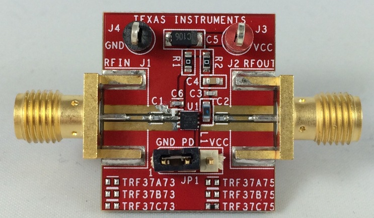
I'm normally a software guy, but a recent project requires me to dip my toe in the ocean of electrical engineering.
I'm trying to (cheaply) capture GPS signals to process in software, and I have an amplifier (TRF37C75 Evaluation Module from TI) for use with an active antenna. What I don't have is a way to inject DC to the coaxial. I'm finding bias tees rated for the appropriate frequency to be too expensive or too hard to get. I'm not of the skill level to build my own from scratch.
An acquaintance of mine suggested that by adding an inductor to the amplifier module, the same as L1 between the VCC and the RFIN side of C1, would have to effect of a bias tee.

This sounds doable, but L1 for this module is a 100nH from CoilCraft; components with this inductance are all SMD, so how do I get it to reach? Can I attach leads to it?
On the other hand, I was also pointed to this blog, where a DVB dongle was modified to add DC to the coaxial. He effectively did the same thing, by adding an inductor between the power supply and the coaxial. By the looks of the images, he just used an insulated copper wire to carry the DC and then soldered the inductor onto the PCB between the capacitor and the coax.
Does this sound reasonable to try with the amp module? It seems rather quick and painless to do, and much cheaper and easier than having to add Yet Another Device (bias tee).
