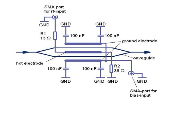
I'm working with a system that requires a ~250-400 MHz modulation signal from 0 to 1.5 V (or -1.5 to 0 V) on an electro-optic modulator (EOM, Jenoptik AM635). I have a signal generator capable of producing the pulses that I need, but it only outputs in the range -0.35 to 0.35 V (can generate pulses with a DC offset). So I need to amplify the pk-pk signal as well as the DC bias, or introduce an appropriate DC bias somewhere else in the circuit. For reference, everything is 50 Ohm termination / input impedance.
Based on my (limited) understanding of RF electronics, I tried the following:
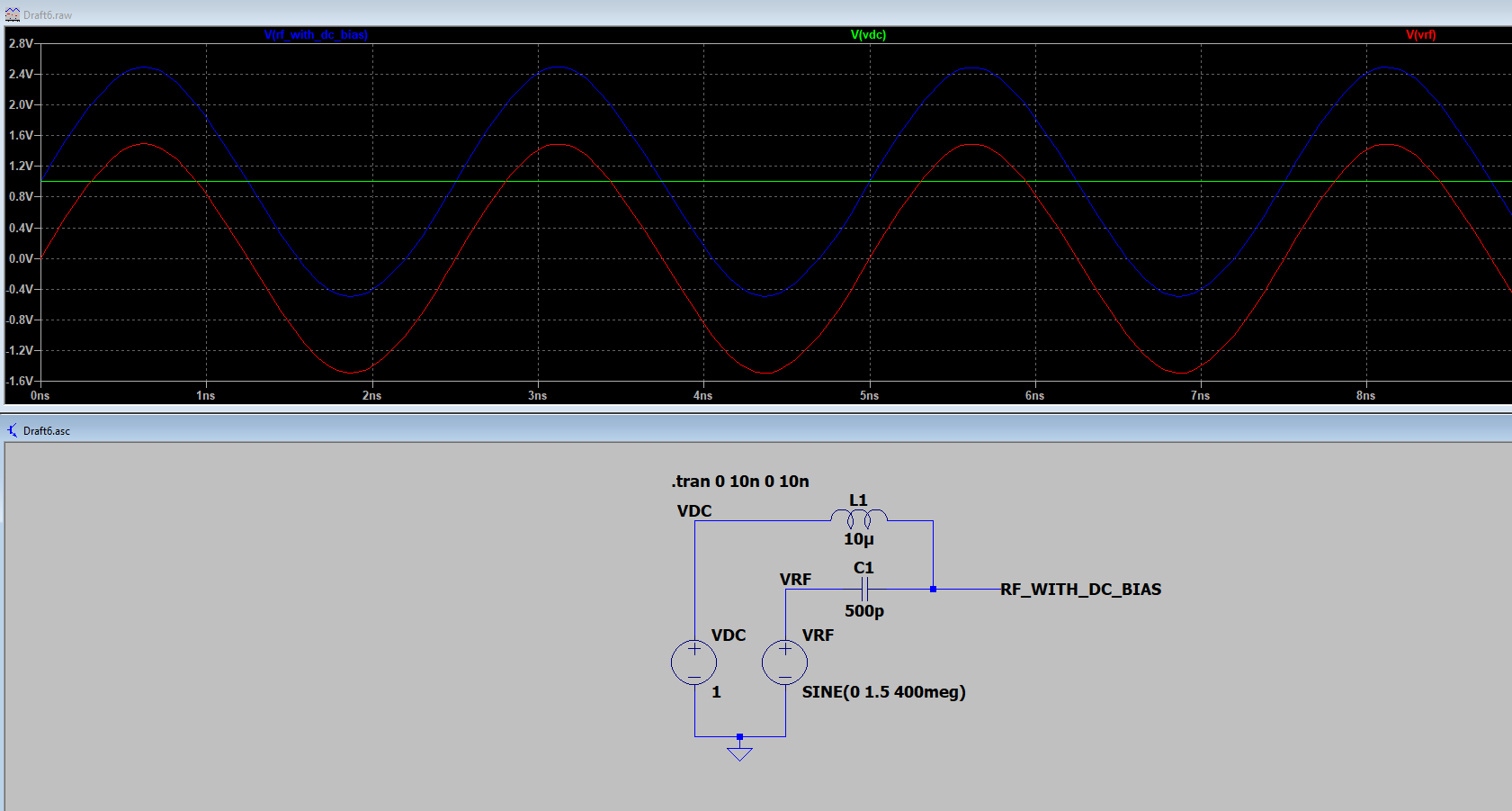
Signal generator (internal clock at 2 GHz) -> Mini-Circuits ZX60-43-S+ (RF Amplifier, 0.5-4000 MHz) -> Mini-Circuits ZFBT-4R2GW-FT+ (Bias Tee, 0.1-4100 MHz) -> EOM (50 Ohm load)
I then adjusted the output from the signal generator to get the correct pk-pk using the AC-coupled amplifier and added the necessary ~0.75 V DC bias on the bias tee. However, this doesn't work and I'm failing to understand why.
When I try to add the DC bias with a 50 Ohm terminated load my DC source hits its current limiter (set to 400 mA to avoid damaging the bias tee) and reaches maybe ~3 mV. When I just plug the output directly into an oscilloscope without a 50 Ohm terminator, the signal looks like what I want without any crazy current draw. I feel like there's something I'm missing here as I don't get why it's so different with and without the impedance matching at the oscilloscope.
Is there a way to modify this system with these components to achieve my desired result (square pulses at ~250-400 MHz that go from 0-1.5 V)? Would I be better served just using a wideband DC-coupled amplifier to begin with (e.g. a DCA-50-08)? Or is there some other option that would work better?


