23
\$\begingroup\$

I have seen a few different ways of adding DC bias to an audio signal. I have simulated them and they all give me similar results, but I can't figure out why choose A over B or C. My audio source will be a Line Level Audio -2V to +2V AC passed through a 220uF coupling cap and then a low pass filter(RC, 2 pole). The signal will be read by an ADC.

First way is using a Voltage divider: Simple Biasing Circuit
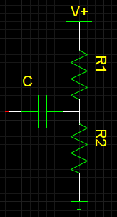
enter image description here

This is pretty self-explanatory and I understand how it works. I have also seen this same design using a diode but could not find an example.

Next example: How to read an audio signal using ATMega328? - picture is from endolith's answer.

enter image description here

Another one that I have seen is: I don't quite understand this FET-BJT preamp circuit

And the schematic is for a pre-amp, and there are 2 versions and both add a bias.
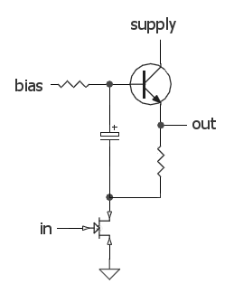
enter image description here

My question is what is the best practice for adding the bias to an audio signal? What are some of the other ways to add a DC bias to the signal?

Edit/Update: Looking at the answers - using the second one looks like it will work best for my application, using something like this. Are there any other improvements I can make? Other then Stable Vref/power rails.
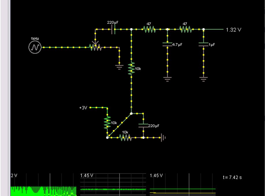
enter image description here

\$\endgroup\$
6
  • 1
    \$\begingroup\$ Small note, you say you have a 220 uF decoupling cap. I think you might be referring to a coupling cap. \$\endgroup\$
    – Kellenjb
    Commented May 18, 2011 at 12:16
  • 2
    \$\begingroup\$ The signal is going to be read by an ADC, for a BPM counter(beats per min) And Kellenjb you are correct coupling cap and not decoupling - fixed \$\endgroup\$
    – jsolarski
    Commented May 18, 2011 at 12:31
  • 1
    \$\begingroup\$ As a note: I use the first solution with no problems but my circuit is definitely not a high fidelity one as it is on a model aircraft with lots of other noise (motors, servo, wind etc.) \$\endgroup\$
    – Thomas O
    Commented May 18, 2011 at 16:11
  • 1
    \$\begingroup\$ You're intentionally trying to isolate low frequencies with those RC filters, right? \$\endgroup\$
    – endolith
    Commented May 19, 2011 at 14:17
  • 1
    \$\begingroup\$ @endolith Yes I am intentionally trying to isolate low frequencies, under 3KHz \$\endgroup\$
    – jsolarski
    Commented May 23, 2011 at 6:08

3 Answers 3

25
\$\begingroup\$

Don't use the first circuit. Any noise or spikes on the power supply will be mixed with your signal. Because the bias point is connected directly to the signal, you can't filter out power supply noise without also filtering out the signal.

Do use the second circuit. It produces a mid-point voltage that is tightly coupled to ground, so the DC component is half the supply, but the AC component (noise and spikes) is filtered out by the capacitor. That's not a complete circuit, though, you still need to connect it to your signal.

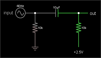
This is what you're trying to do:

simple DC biasing

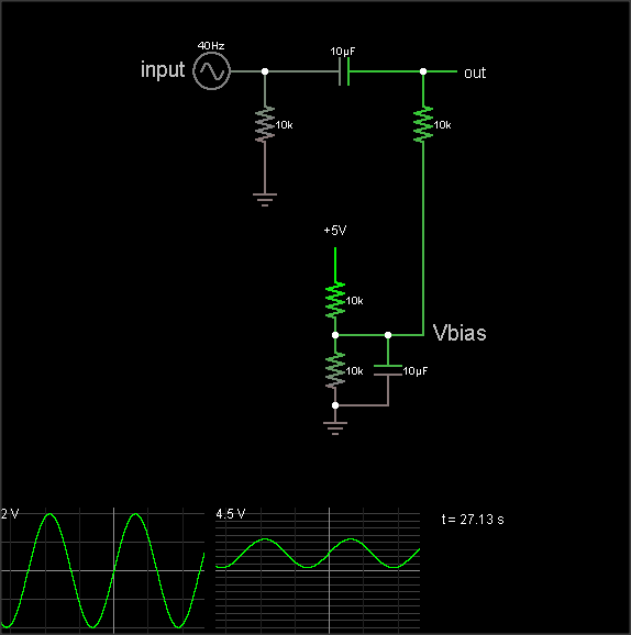
The output is the same as the input, just shifted upward by 2.5 V. The resistor on the input ensures that the input side of the capacitor is already at 0 VDC bias when an external circuit is connected, to prevent "pop" sounds (if the voltage suddenly jumped from 2.5 V to 0 V). The resistor on the output side of the AC coupling cap biases that side to the DC bias voltage. If your circuit already has a clean, low impedance DC bias voltage source, connect to that. Otherwise, you can use circuit #2 to generate the bias, like this:

Circuit showing DC biasing of an AC signal

(The simulation takes a loong time to reach the DC bias value, though. Hit the "Find DC operating point" menu entry to settle it.)

The DC bias voltage is produced by a voltage divider and capacitor to filter out power supply noise. Note that if you use the same Vbias point for multiple signals, they can crosstalk through this point. Larger bias cap reduces crosstalk. Larger coupling capacitor improves low frequency response. But make them too large and they'll take a long time to charge when you flip the power switch.

The 3rd diagram is not a biasing circuit; it's a microphone preamplifier.

\$\endgroup\$
10
  • 1
    \$\begingroup\$ @jsolarski: It'll be like any audio mixer input, then. You'll need some variable gain control for the unpredictable low-level inputs, and maybe separate jacks for the line-level, depending on the connectors you want to use. For a BPM counter, low-noise probably isn't that important, so you could just use a single op-amp gain stage with a wide gain range. Alternately, a narrower gain range and a 20 dB pad switch. \$\endgroup\$
    – endolith
    Commented May 23, 2011 at 14:06
  • 1
    \$\begingroup\$ @endolith "The resistor on the input ensures that the input side of the capacitor is at 0 VDC, to prevent pops during connection." can you please explain it a little bit more for me? is this to discharge the capacitor? why it may pop? what will happen if I leave it? Sorry if the questions are silly. \$\endgroup\$ Commented May 13, 2020 at 16:38
  • 1
    \$\begingroup\$ @SouravGhosh If that resistor weren't there, and the input was not yet connected, and you turned on the power, then both sides of the capacitor would rise at the same time until they were at Vbias=2.5 V. If you then connected a device that had an output resistance of 100 Ω, for instance, connected to ground, then the input side of the capacitor would be instantly pulled close to 0, causing the output of the capacitor to jump to 0 as well, producing a pop sound. Then the capacitor would slowly charge through the 100 Ω and 10 kΩ resistors until the input was 0 and the output was 2.5 V \$\endgroup\$
    – endolith
    Commented May 13, 2020 at 19:50
  • 1
    \$\begingroup\$ @endolith Thank you very much. Now it is quite clear. I also visited your circuit simulation, removed the input and the resistor, decreased simulation speed, and verified this behavior. At first, I was confused after reading your answer because I thought you were talking about capacitor popping (i.e, destruction of the capacitor). Now I understand that it is the 'pop' sound that we get sometimes after connecting a speaker. \$\endgroup\$ Commented May 14, 2020 at 9:49
  • 1
    \$\begingroup\$ @SouravGhosh Ah, yes, I'll clarify \$\endgroup\$
    – endolith
    Commented May 14, 2020 at 16:13
9
\$\begingroup\$

The simplest method is the first image you linked to. It will do the job, but has a big draw back for your application. If your supply lines have any noise on them, the noise will be added to the signal you are trying to measure.

The second method is almost identical to the first method. It's big advantage over the first method is that noise on the supply lines wont have as big of an effect on the signal itself.

The third method is over kill for what you are wanting to do. It is designed to give higher power outputs, but since you are just reading it with an ADC there is no reason you need it.

\$\endgroup\$
1
  • 2
    \$\begingroup\$ If the voltage from which the ADC derives its reference feeds the resistor divider, I don't see that having that voltage coupled into the audio feeding the ADC will be much of a problem. Indeed, if there's any wavering in the ADC reference, I would think having it coupled to the ADC input with 50% amplitude would be better than having the reference move and the input not, although the audio signal would be degraded in any case. If the ADC reference is an absolute voltage which is not available on an output pin, your bias should likewise be an absolute voltage (from a regulator or whatever). \$\endgroup\$
    – supercat
    Commented May 18, 2011 at 16:42
6
\$\begingroup\$

The first circuit, the simple resistor divider, is by far the easiest, quickest, and cheapest solution. It is also the solution that most audio circuits use. Unless you are wanting pro-audio levels of performance, this is the method that I would recommend.

The "correct" solution would be to have a separate power rail that is at the bias voltage. Run your audio signal through a DC blocking cap then have a resistor to the bias power rail. This approach has less noise and harmonic distortion than the simple resistor-divider-- although the difference in performance is only important for those in the pro-audio world and not worth bothering with for most.

One case where the "correct" solution is worth the trouble for the average circuit is when the ADC itself provides the bias voltage rail. Some ADC's will output that voltage and all you have to do is use it. This is nice because you can get better precision than any other solution. Sometimes I have had issues, however, where I had to take this output from the ADC and run it through a unity gain op-amp based buffer so it had the drive strength to work properly.

The other two solutions you mention would work, but I wouldn't bother. They are somewhat tweaky and don't offer any important benefits that the simple resistor-divider or the "correct" solutions provide.

\$\endgroup\$

Your Answer

By clicking “Post Your Answer”, you agree to our terms of service and acknowledge you have read our privacy policy.

Not the answer you're looking for? Browse other questions tagged or ask your own question.