0
\$\begingroup\$

schematic

simulate this circuit – Schematic created using CircuitLab

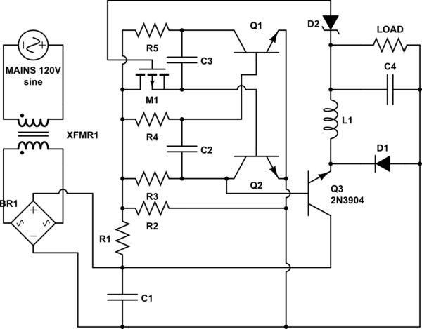
This is my rough sketch for a buck converter controlled by a BJT based astable multi-vibrator with zener-based feedback. Before I go through getting the values of each component, I wanted to make sure that I understand how these components would work in my circuit, and if I've done anything dangerous here.

Theory of Operation:

1) The mains go through a transformer which brings it down to 20-25V AC. This also has the effect of isolating the circuit from earth-ground.
2) The bridge rectifier BR1 converts the AC into full-wave DC.
3) C1 is a giant electrolytic which smoothes the DC wave into "constant" DC.

Oscillator:
1) R1 and R2 form a voltage divider which provides 5V to the oscillator. It is acceptable to use a voltage divider because the load of the oscillator will be known, and the current it draws will be relatively low. Our efficiency is not completely compromised due to this, and we don't get an unmanageable production of heat.
2) The 5V is fed into a standard BJT astable oscillator, with one exception. The low-value resistor which dictates the RC time constant of C3 is replaced by a P-Type Mosfet which acts as a variable resistor. Variation in the current on the gate of the Mosfet will change the RC time constant of C3, effectively modulating out pulse width if we apply feedback.
3) The collector of Q2 is used as the input to our buck converter.
4) D2 is a reverse bias zener diode. If the voltage goes above 12V then the zener will allow current through. This current will be sent to the gate of M1, the "variable resistor" Mosfet from step 2. D2 is placed in reverse bias directly to the load. This channel is used as feedback.

Buck Converter:
1) An NPN BJT (Q3) is being used as a switch. Since we're dealing with 5V logic, saturation shouldn't be an issue.
2) L1 evens out changes in current, while C4 evens out changes in voltage. This averages the input.
3) D1 prevents a massive negative voltage surge from destroying the BJT switch Q3 when Q3 goes from on to off.

Question:
Is there anything wrong with the theoretical version of the circuit, barring that it needs to have values applied to the components?

\$\endgroup\$
8
  • 1
    \$\begingroup\$ "If the current goes above 12V" - do you mean voltage? and you might like to check where (and how) D3 is connected. The time constants for the multi vibrator are controlled by R6C3 and R7C2 not the collector load resistor you have replaced with a MOSFET so I seriously doubt if your circuit will work. \$\endgroup\$ Commented May 25, 2015 at 14:29
  • \$\begingroup\$ Yes. I meant voltage. I'll change that momentarily. I will also change my circuit diagram to compensate for misplacing the time-constant resistor. \$\endgroup\$
    – Allenph
    Commented May 25, 2015 at 14:34
  • \$\begingroup\$ @JImDearden, I've vastly improved the diagram for readability, and I've also made a correction to the error you pointed out. \$\endgroup\$
    – Allenph
    Commented May 25, 2015 at 15:11
  • 1
    \$\begingroup\$ You MUST learn to draw schematics in a more conventional manner.MUST. Energy flow generally left to right. Do not spiral or zigzag etc. Controller generally above or below energy flow ccts BUT that is not a "rule" per se. \$\endgroup\$
    – Russell McMahon
    Commented May 25, 2015 at 15:16
  • 2
    \$\begingroup\$ Q3 will be have to switch at least twice the current at the output but the last time I checked the 2N3904 is just a small signal device (a few 100mA). Normally a P channel MOSFET with low Rds and reasonable current carrying capability (a few amps) is used. Here's a circuit similar to yours. You may get some ideas from it. Note how it controls the mark/space ratio (and hence the output voltage) and how it turns the current switch transistor ON and OFF. electro-tech-online.com/customimages/2011/09/… \$\endgroup\$ Commented May 25, 2015 at 16:23

1 Answer 1

1
\$\begingroup\$

It's a poor circuit design. Q3 is an emitter follower and therefore the maximum voltage that can be fed to the output inductor is somewhat less that the DC voltage from the bridge smoothing capacitor. R1 and R2 set this voltage and maybe it's 1 or 2 volts below the Vcap voltage or maybe it's more.

Even with R1 shorted out and R2 omitted, the rise time of the multivibrator will not be that sharp and this will create significant switching losses in Q3 - these losses add to the conduction losses due to Q3 being an emitter follower.

This would mean to me that the design should be scrapped - there are too many things to put right to get an efficient switching regulator from the bones of the current circuit.

If you decide to try and fix things up by going thru a series of modifications with the inevitable series of further questions, count me out. I've told you what is wrong with it and you should see the light.

\$\endgroup\$
5
  • \$\begingroup\$ Always a ray of sunshine. But, you did answer my question and I appreciate that. I don't expect you to respond, but we'll give it a go. The collector of Q3 is not grounded through C1 since it is in parallel (I think) and from what I gathered from your answer it is grounded through the voltage divider. Recently I did a tear down of an old buck-converter SMPS. Inside was an EL817 photocoupler. Could I use a similar photocoupler to supply the controller circuit with current and thereby isolate Q3's collector from ground? \$\endgroup\$
    – Allenph
    Commented May 25, 2015 at 20:03
  • \$\begingroup\$ As for your comment about scrapping the circuit, perhaps I should...but...it's the only way I can come up with to accomplish the task I'm looking to accomplish, spending the time to understand what's wrong and how I would fix it will lead me to better understand how to improve future circuits. \$\endgroup\$
    – Allenph
    Commented May 25, 2015 at 20:08
  • \$\begingroup\$ Eh?? Q3's collector connects to the most postive part of the dc circuit. As for your aims, they are good and I applaud that BUT (unfortunately) the Q and A part of the site is not suitable for an evolving suggestion-correction format. If you kept getting tips on what to change your question evolves and makes answers previously given redundant. It is very important that answers match questions or else someone coming along in a week or a year will look at your question and raise eyebrows over the answers that don't make sense anymore. Move on with a fix and raise a new question is my advice. \$\endgroup\$
    – Andy aka
    Commented May 25, 2015 at 20:42
  • \$\begingroup\$ I was worried that doing so would be result in questions being marked as a duplicates. I.E., it would result in a thousand questions "Is it right now?", "How about now? Is it right now?", "I think I got it this time. Is it right now?" The number of times I've asked a question about this project is pushing the limits already in my mind. Is it acceptable to continually ask similar questions? Perhaps I should isolate circuit issues with questions THEN move on to "Is it right now?" Your music is very Pink Floyd, by the way. \$\endgroup\$
    – Allenph
    Commented May 25, 2015 at 20:48
  • \$\begingroup\$ Perhaps these comments belong in meta, or a private chat. If you would be so obliged, I would love for you to join me in chat...chat.stackexchange.com/rooms/24115/a-room-for-andy-and-allen \$\endgroup\$
    – Allenph
    Commented May 25, 2015 at 20:50

Your Answer

By clicking “Post Your Answer”, you agree to our terms of service and acknowledge you have read our privacy policy.

Not the answer you're looking for? Browse other questions tagged or ask your own question.