0
\$\begingroup\$

I am using a PIC to drive the gate of a logic level MOSFET. Although the 5V logic output of the pic is sufficient to exceed the threshold voltage I would like to drive the gate using 12V to reduce the Drain-Source resistance.

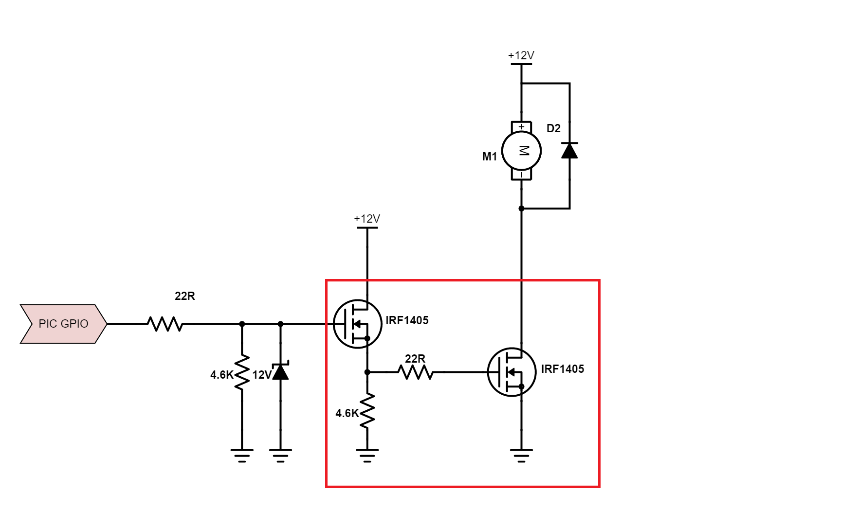
In order to achieve this I have drawn up the following circuit using two MOSFETs in series (as highlighted). Will this design work, and is it the best approach (keeping in mind i want to minimize the number of components).Example of Series MOSFETS
\$\endgroup\$
4
  • \$\begingroup\$ Which zener are you using . Please provide the component identification number. \$\endgroup\$ Commented Aug 30, 2015 at 4:14
  • \$\begingroup\$ Hi Abhishek, chosen zener will be 1N4742. However I dont believe the zener chose will change the answer to the question. \$\endgroup\$ Commented Aug 30, 2015 at 4:20
  • \$\begingroup\$ The circuit as shown will give the output FET lower gate drive voltage than if you just connect the output gate directly to the PIC GPIO. If you change the first FET to have a grounded source and put the 4.6K resistor and the output gate connection into the drain circuit of the first FET you will get the increased gate drive you are after. This will also invert the sense of the PIC output relative to motor on/off. \$\endgroup\$ Commented Aug 30, 2015 at 9:27
  • \$\begingroup\$ Thanks Michael Kara's! Your answer was very insightful and the suggested change would work for my purposes. \$\endgroup\$ Commented Aug 30, 2015 at 11:02

2 Answers 2

3
\$\begingroup\$

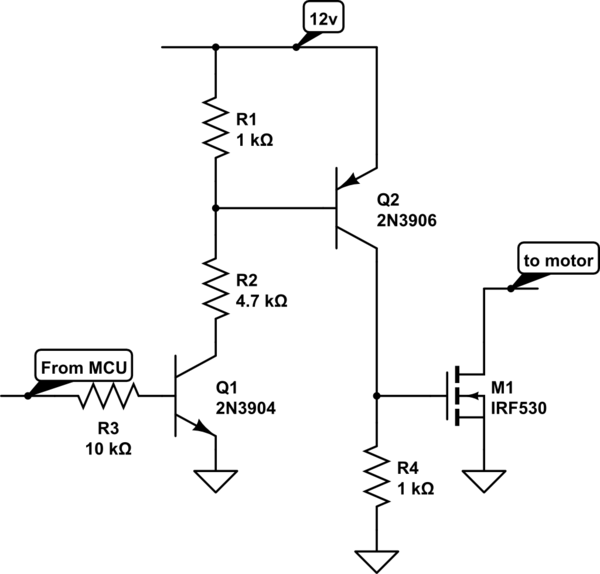
This doesn't drive the output MOSFET with a higher gate voltage - it will only see about 2V as the first MOSFET is acting as a source follower - the 5V from the MCU will be reduced by the threshold.

To drive the output stage with a higher voltage will require a couple of stages. Something like the following schematic. Bec careful about exceeding the VGS of the output stage.

You don;t say if you are using PWM modulation, if you are you will need to ensure fast charge and discharge of the MOSFET gate capacitance - this circuit may not be adequate.

schematic

simulate this circuit – Schematic created using CircuitLab

\$\endgroup\$
6
  • \$\begingroup\$ Thank you for the answer! however wouldnt it only act as a sorce follower if the source of the first MOSFET was connected to the drain of the second? \$\endgroup\$ Commented Aug 30, 2015 at 4:58
  • \$\begingroup\$ This is how I would do it, +1 \$\endgroup\$
    – KyranF
    Commented Aug 30, 2015 at 7:37
  • \$\begingroup\$ @user3095420 No - the input signal goes to the gate and the output is taken from the source of the first MOSFET. That makes it a source follower. Its gain is less than unity. \$\endgroup\$ Commented Aug 30, 2015 at 16:16
  • \$\begingroup\$ @KevinWhite could you explain what the purpose of R1 is? \$\endgroup\$ Commented Aug 31, 2015 at 1:47
  • \$\begingroup\$ R1 is to help Q2 turn off. It provides a path for charge from the base to return to the emitter. Without it the turn off would be excessively slow. \$\endgroup\$ Commented Aug 31, 2015 at 3:26
2
\$\begingroup\$

The real question here is how much current will need to pass through the motor.

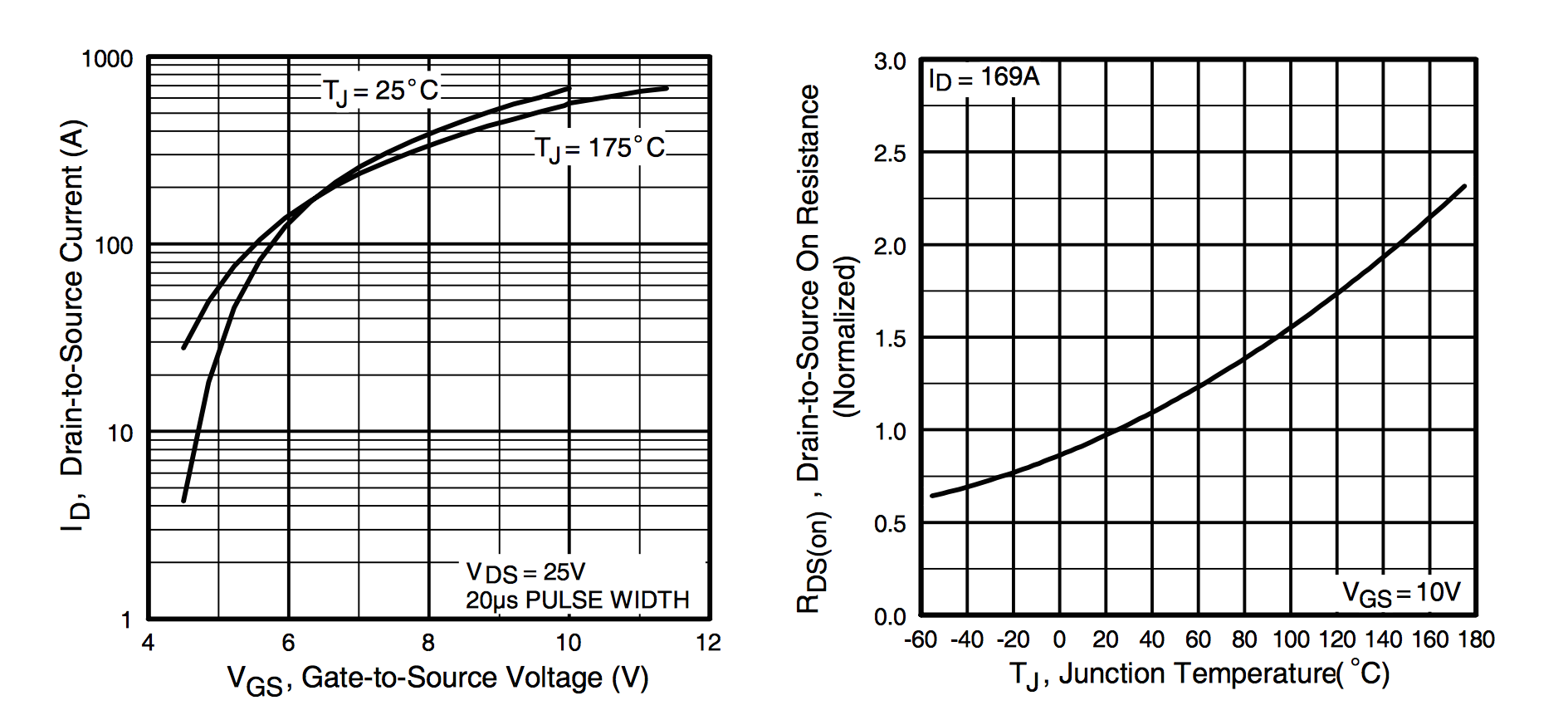
If you look at the datasheet for the IRF1405 mosfet, you should see two very important graphs:

enter image description here

The graph on the left shows that the mosfet can pull up to 60A of current when the gate voltage is 5v. So, if your motor pulls less than 60A, you would be fine with a single mosfet. If you need over 60A, you could use 2 mosfets and get the rated 169A.

The graph on the right shows how the Drain-Source On Resistance is related to the temperature. This is important because if you can predict the temperature, you can predict the voltage drop across the mosfet.

In summary: Yes, the proposed circuit will work, but the job can be done with a single mosfet if it is pulling under 60A. (Or you could look for other mosfets that have different gate voltage - drain to source current.)

\$\endgroup\$

Not the answer you're looking for? Browse other questions tagged or ask your own question.