0
\$\begingroup\$

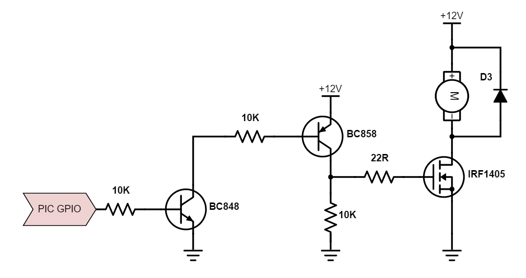
I would like to drive a MOSFET gate using 12V (in order to reduce the drain-source resistance). Using the answer from a few post i've read I have come up with the following circuit. Will this circuit work for an application where i will be switching the motor on and off one every 10 minutes?

Further more is this the best method of driving the FET? and is there any type of "MOSFET driver IC" i can use to reduce space on my PCB? enter image description here
\$\endgroup\$
7
  • \$\begingroup\$ You asked a somewhat similar question electronics.stackexchange.com/questions/188096/… and one of the answers includes a schematic to drive your motor. The circuit you presented has a problem when PIC GPIO = 0 \$\endgroup\$
    – efox29
    Commented Aug 30, 2015 at 14:24
  • \$\begingroup\$ What current does the motor take? \$\endgroup\$
    – Andy aka
    Commented Aug 30, 2015 at 14:24
  • \$\begingroup\$ motor will take up to 20A \$\endgroup\$ Commented Aug 30, 2015 at 14:25
  • \$\begingroup\$ Hi efox29, Yes this question is similar. However i have modified my question based on the answers I had received. The circuit presented in this question also is different to the one provided in the answers and hence i wanted to check that It would still work with the modifications i had made \$\endgroup\$ Commented Aug 30, 2015 at 14:31
  • 1
    \$\begingroup\$ Google "gate driver ic". \$\endgroup\$ Commented Aug 30, 2015 at 14:31

1 Answer 1

2
\$\begingroup\$

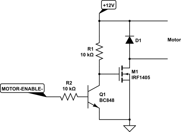
I would use the following circuit. It cuts down on parts from the given schematic. This is probably as tight as it gets in terms of board space. R1, R2 can be as small as you care to solder.

schematic

simulate this circuit – Schematic created using CircuitLab

\$\endgroup\$
5
  • 1
    \$\begingroup\$ Note that your circuit requires an active-low motor enable signal. \$\endgroup\$
    – Dave Tweed
    Commented Aug 30, 2015 at 15:03
  • \$\begingroup\$ Good point @DaveTweed. Handle accordingly in the code. \$\endgroup\$ Commented Aug 30, 2015 at 15:05
  • 1
    \$\begingroup\$ Sorry, but I wouldn't use this circuit. The reason: when the PIC is not driving its output (for example, when it's being reset), this circuit will switch on the motor, which, IMHO, is not a safe design. To save a single trasistor and a resistor... \$\endgroup\$ Commented Aug 30, 2015 at 16:49
  • 1
    \$\begingroup\$ Where a known initial state is required, a pull-up should be used. \$\endgroup\$ Commented Aug 30, 2015 at 16:54
  • \$\begingroup\$ @HoustonFortney or pull down. \$\endgroup\$
    – efox29
    Commented Aug 30, 2015 at 18:51

Your Answer

By clicking “Post Your Answer”, you agree to our terms of service and acknowledge you have read our privacy policy.

Not the answer you're looking for? Browse other questions tagged or ask your own question.