Short answer before derivations:
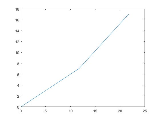
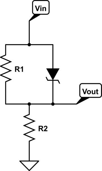
The voltage Vout will increase linearly with value (R2/(R1+R2))*Vin, until the input value reaches Vz*((R2+R1)/R1) or equivalently the output voltage Vout is (R2/R1)*Vz, then any change in the input voltage will be reflected as an increase in the output voltage while the voltage across the Zener and R1 will be kept constant at Vz. The reason for that is that R1 will reserve for itself Vz/R1 current passing through it and the rest will pass through the Zener.
Visualization:
Ranges 1 and 2

R1 = 10 ; % as an example
R2 = 15 ; % as an example
Vzen = 4.7; % as an example

VinTh  = Vzen\*((R2+R1)/R1); % The X-axis Value of the point at which the slope will change
VoutTh = Vzen\*(R2/R1);      % The Y-axis Value of the point at which the slope will change

VinChange = 10   ;         % any change in input voltage after the threshold
                           % point
                           % 5 is an example
VoutChange = VinChange ;   % after the threshold point the Zener will keep
                           % for itself and for the resistor R1 a constant
                           % voltage of Vz any excess increase in Vin will
                           % be reflected to the same increase in R2 , keep
                           % in mind that the resistor R1 keep (Vzen/R1) Amp
                           % for itself and the rest of current pass
                           % through the zener to satisfy the increase in
                           % voltage across R2

Vin  = [0 VinTh VinTh+VinChange] ;
Vout = [0 VoutTh VoutTh+VoutChange] ;
plot(Vin,Vout);
Derivations:
- Before the threshold point is reached:
(Vout / Vin) = (Vout / (Vz+Vout)), Vout inn numerator cancels out from both sides
Vin = Vz+Vout ----> 1
Vout = Vin*(R2/(R1+R2))
Vin = Vout ((R1+R2)/R2) -----> 2
from 1 , 2 we get:
Vout = Vz*(R2/R1) using same logic we can get at that point the input voltage should be:
Vin = Vz*(R2+R1)/R1 ;
- Once the voltage across the resistance R1 reaches Vz, the Zener will start passing current and keeping the voltage across it at Vz, any increase in input voltage will be reflected as in increase in the output voltage.
In Brief:
The slope of the first segment is (R2)/(R2+R1), while the slope of second segment is 1.
EDIT: For the reverse direction you will follow the same logic except that the drop in opposite direction across the Zener will be 0.7 V typically [Rang 0.]


