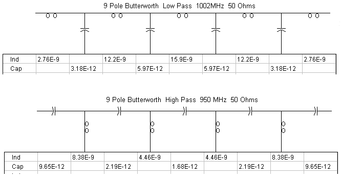
I want to design 1002MHZ low pass and 950MHZ high pass filter. It is a tv/sat combiner. I calculated the parameters for a butterworth filter like below, but it didn't work. How can I fix this design?
-
1\$\begingroup\$ "it didn't work" is a bit too vague for debugging purposes... \$\endgroup\$– user16324Commented Oct 20, 2015 at 18:43
-
\$\begingroup\$ i wanted to add my spectrum screenshot Unfortunately my spectrum trigger is broken and i have to use modulator for input signal so i didnt add screenshot \$\endgroup\$– Sercan CobanCommented Oct 20, 2015 at 18:46
-
\$\begingroup\$ i think i am beginner at rf maybe i did a big mistake so i want to ask experienced people \$\endgroup\$– Sercan CobanCommented Oct 20, 2015 at 18:49
2 Answers
When you design a diplexing filter from a prototype lowpass and highpass filter, it's important to get the terminating resistances correct. I see from your symmetrical filter designs that they are matched to finite impedances on both ports.
If you design a (for instance) lowpass filter with (say) 50ohms impedance on each port, then as you swing the input frequency over a wide range, you will see the filter input impedance change. In the passband, it will be 50ohms (+/- a bit). In the stopband, it will tend to zero or infinity, depending on whether the filter is L or C input.
Now in a diplexing filter, this doesn't happen at the common port. This stays matched regardless of frequency. At low frequencies, the lowpass filter matches it ( as long as the highpass is series capacitor input). At high frequencies, the highpass filter matches it (as long as the lowpass filter is series inductor input). That means the voltage on that port stays constant as the frequency changes.
So the common port is not conventionally 50ohm matched. In fact, you need to design your component filters to match, at the common port, into a short circuit. This is the correct model that will work with constant voltage regardless of frequency. (I had trouble getting my head round this at first)
Most filter design packages will give you the option of specifying the port match. Design the component filters for zero ohms and a series component on the common port, and 50 ohms on the isolated port.
Let us know how you get on.
By the way 'doesn't work' is a rubbish thing to say, it will get you down-votes. The circuit did something, say what it did. You were expecting x, you measured x, it worked. You were expecting x, you measured y, it didn't work, so what were x and y? What was the inserting loss at the cross-over frequency, and far from it? What were the port matches at the cross-over frequency, and far from it? And what were you expecting?
And nineteenthly (english-speaking joke, sorry), if you want to separate 1002MHz and 950MHz, you will need more than a few Ls and Cs, and, frankly, some RF experience to make it work. The difference between those two frequencies will need very high Q filters to make it work.
-
\$\begingroup\$ thanks for your answer, when i searched on the net i saw a different design. they say (if you think my shematic) you should add a resistor from RF_S to RF_T \$\endgroup\$ Commented Oct 20, 2015 at 19:14
-
\$\begingroup\$ Resistor from RF_S to RF_T? That's a different design, a different concept. That's isolators. Which is not to say that won't help you out of your 'lack of Q for the frequency difference' problem. I could believe that with the right phase shift through your filters, a resistor there could enhance rejection of the other signal, over a narrow band, try it on a simulator. But try the proper impedance diplexer design first. \$\endgroup\$– Neil_UKCommented Oct 20, 2015 at 19:18
-
\$\begingroup\$ okey, i got it, i am glad to you i will try your suggestion thanks again. \$\endgroup\$ Commented Oct 20, 2015 at 19:20
I don't think this is close to a realistic design, but you asked whether the values are correct for a Butterworth filter, and I don't believe they are. At least not if both the input and output are terminated in 50 Ohms. Try these values instead.

-
\$\begingroup\$ if they are symmetrical, they are not going to work in a diplexer \$\endgroup\$– Neil_UKCommented Oct 20, 2015 at 20:46
-
\$\begingroup\$ I was just trying to answer the question as to whether the OP had made a mistake in his basic filter calculations. i.e. A basic Butterworth low pass and high pass. He needs to solve 1 problem at a time. \$\endgroup\$ Commented Oct 20, 2015 at 20:59


