-1
\$\begingroup\$

I'm currently trying to reverse the voltage at a DC motor ports, from 5V to -5V, to invert its rotation.

I also want to be able to have 0V at theses ports.

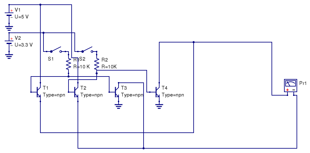
I have a micro-controller that is able to give 3.3V output on one of its pins, represented as S1 and S2.

Here is what I've tried

The voltage at the Pr1 meter is :

  • 0.3V when S1 is closed and S2 is open
  • -0.3V when S2 is closed and S1 is open
  • 0V when both are open

I'd like to have 5V voltage, what did I do wrong ?

By the way, is there an easiest way to do that ?

\$\endgroup\$
4
  • 1
    \$\begingroup\$ You apply ~3.3 V at the base of T1 (for example). Why do you expect the emitter to go above ~2.7 V? \$\endgroup\$
    – The Photon
    Commented Nov 14, 2015 at 19:10
  • \$\begingroup\$ Is that an H-bridge? Must the most confusing diagram of one I've seen in a while... \$\endgroup\$ Commented Nov 14, 2015 at 19:12
  • \$\begingroup\$ At your level of experience you should probably just build one with two PNPs and two NPNs as shown as the first figure in electronics.stackexchange.com/a/200449/54580 To use NPN as output transistor on the high side requires more design/thinking (as in the 2nd figure for example). \$\endgroup\$ Commented Nov 14, 2015 at 19:18
  • 2
    \$\begingroup\$ @ThePhoton : no, given T3 b-e junction, he actually applies about 0.7V at T1 base. \$\endgroup\$
    – user16324
    Commented Nov 14, 2015 at 19:23

2 Answers 2

3
\$\begingroup\$

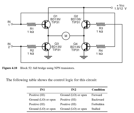
If you want to make an all-NPN H-bridge, the schematic and associated logic is as follows:
enter image description here

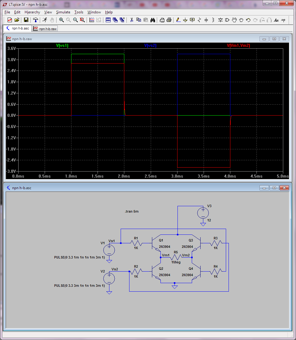
Do not use these power transistors straight from a uC though. You will not be able to saturate them and they will likely burn. Lower power transistors will work though, beta in saturation is about 10. Also this circuit doesn't show any flyback diodes, so it's just conceptual. Furthermore, with an NPN H-bridge, you cannot exceed (at the motor) the voltage of your driving signal (so at most +/-3.3V); note that this happens even if I use a much larger value for the H-bridge's own supply (like 12V):
enter image description here

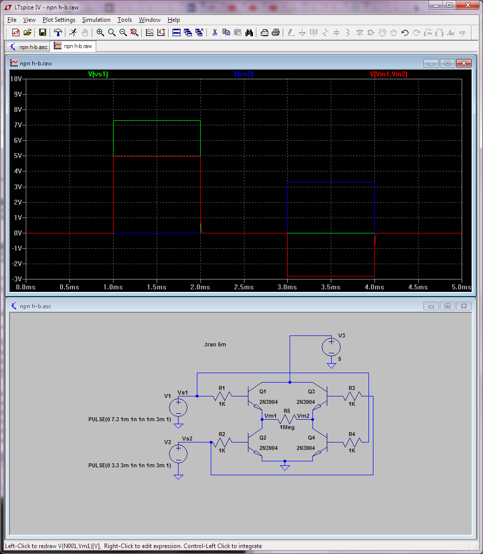
To actually get 5V at the motor, your signal needs to drive the transistor's bases above Vcc, like below for example where I've changed the first signal to 7.3V:
enter image description here

That's why all-NPN H-bridges aren't so popular.

So in case you wonder what's the advantage of PNPs on the high-side... First let's see what would look like...
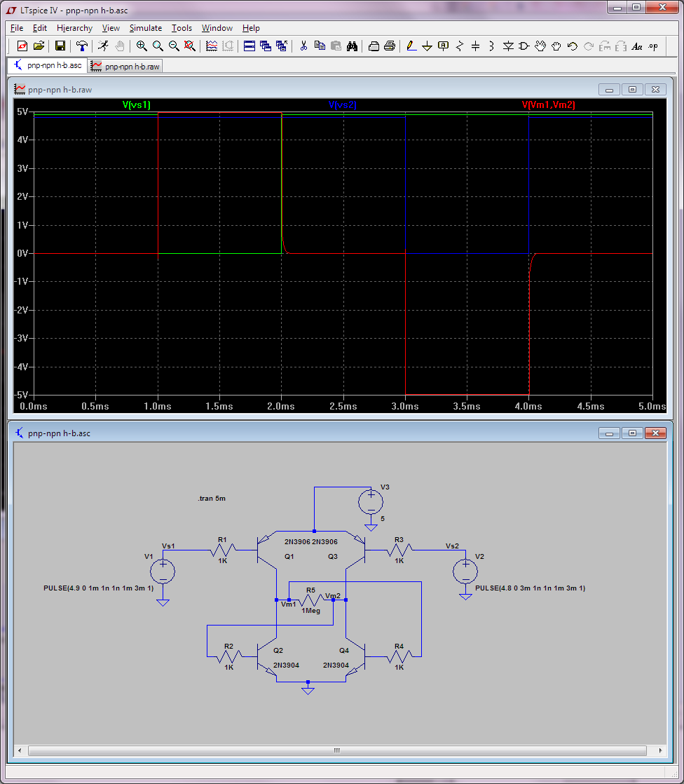
enter image description here

Note that the input signals are now active low... and you need to keep them at (5v) rails on "off". I've fuzzed their values a little bit (4.8 and 4.9V) so you so you can see them clearly on the graph. Doesn't look like much of an advantage just like this, that's why you normally see another transistor in front of them (to inverse the logic and do logic level translation) as shown below:
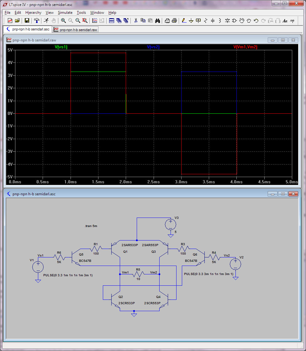
enter image description here

Now you can drive this with 3.3V logic and get 5V at the motor. Also note that this circuit needs a proper (low resistance) load to actually work. MOSFETs class next week... Actually you can look at these lab notes for the MOSFET equivalent of this latter circuit.

And in case it wasn't obvious, the easiest thing is to use an H-bridge made by somebody else, like an integrated circuit H-bridge of which there are many you can buy.

\$\endgroup\$
2
  • \$\begingroup\$ Before building this it is worth considering that at only 5v in the drop in a bipolar bridge will be quite notable - a modern MOSFET bridge like a TB6612FNG would perhaps be preferable. \$\endgroup\$ Commented Nov 14, 2015 at 19:49
  • \$\begingroup\$ @Chris Stratton: Yes, this won't be a great thing, except as learning device. But L293D sells like hot cakes to DYI, so... \$\endgroup\$ Commented Nov 14, 2015 at 19:53
2
\$\begingroup\$

Consider a case ,say S1 is closed and S2 is open .Transistors T2 and T4 are OFF and virtually absent from the circuit . The base of T3 will be pulled to 3.3 V so the transistor will be in hard saturation. Thus, the output at its collector will be Vce(saturation) i.e. 0.3 V above ground and the transistor will conduct the maximum current .This output is the negative terminal of your voltmeter .

A similar thing would have happened at T1 but notice there is no path to ground from the emitter of T1 as T4 is OFF .Thus, KCL isn't obeyed. Therefore,T1 will also remain OFF . As a result the positive terminal of your voltmeter i.e emitter of T1 will be at zero volts .Therefore ,you must get -0.3 V as output (?? are you sure the voltmeter was hooked the same as it is in schematic) .

I advice you to use an H-bridge circuit for driving the motor in both directions .You can get a lot of them at Talking electronics.com . Also don't forget to use free-wheeling diodes to protect your transistors against back-emf of your motor.

\$\endgroup\$

Your Answer

By clicking “Post Your Answer”, you agree to our terms of service and acknowledge you have read our privacy policy.

Not the answer you're looking for? Browse other questions tagged or ask your own question.