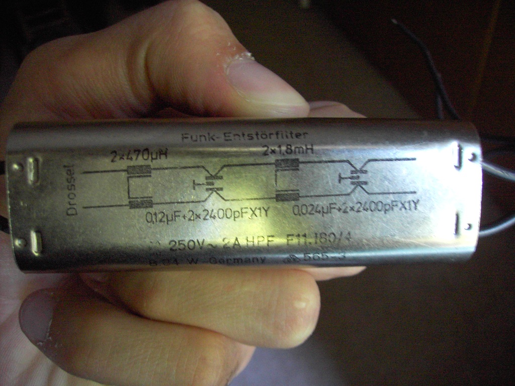
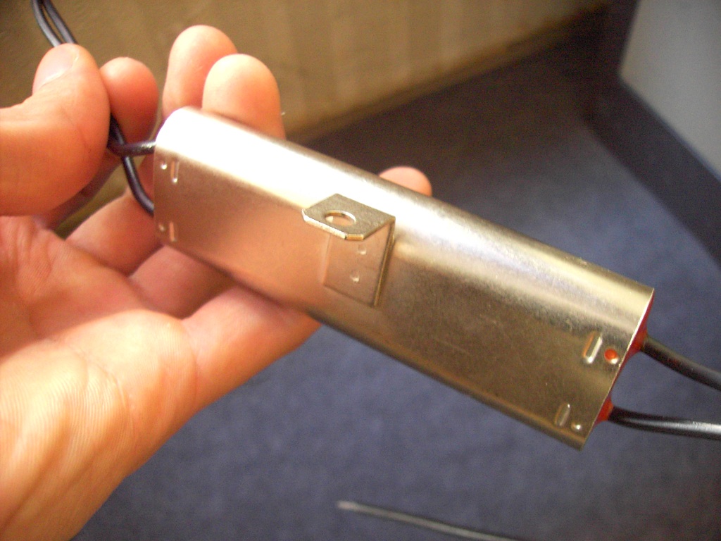
I have a filter that has these on it:
Funk-Entstörfilter
Drossel
250V~2A HPF F11.180/4
8.84 W Germany 565-3


I also added a picture. In the picture, you can see that there is a circuit diagram, however I can't understand this diagram. In example, how the capacitors are connected? Do these lines that connects inductors mean that they are coupled? I don't know much about it but can they be common mode chokes?
Can you convert this into a schematic that I can understand?
