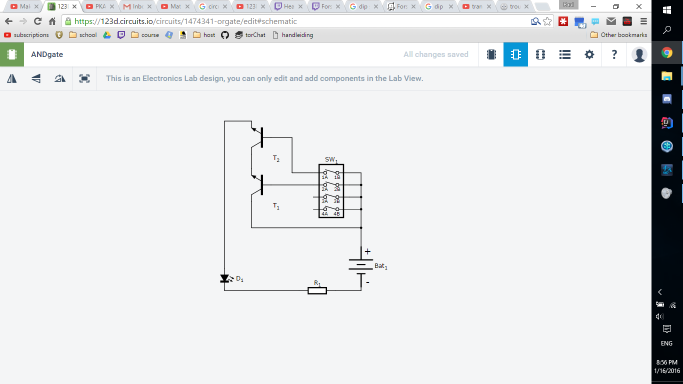
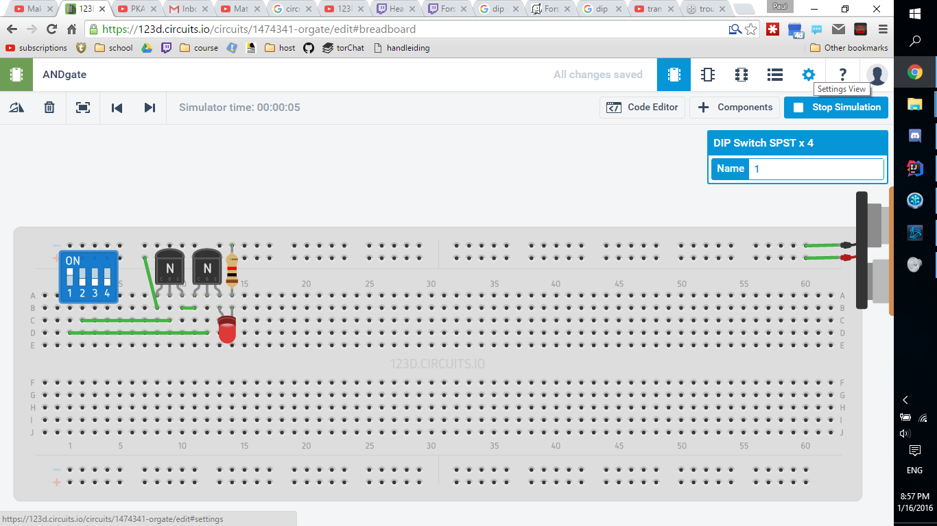
i'm having trouble with making an AND gate on this circuit simulator website 123 circuits. This supposed to be AND-gate only responds to input from switch 1 on the dipswitch and 2 doesnt affect it at all. Am i doing something wrong or is this application bugged?
 notice the led being lit while only 1 switch is toggled on

-
\$\begingroup\$ First off your schematic diagram is upside down. Learn why this is important and you will be well on your way to better understanding the circuit. \$\endgroup\$– Michael KarasCommented Jan 16, 2016 at 23:13
2 Answers
When you turn on the upper switch, current passes directly from the base to the emitter of transistor T2, lighting the LED. In this mode, the transistor is functioning as a diode.
When you turn on the lower switch, the same thing would happen with T1, except that T2 is not passing any current, keeping the LED from lighting.
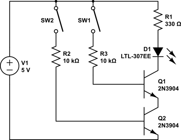
If you put the LED in series with the collector of T1, you'll get the effect you're looking for — but now you also need additional resistors to limit the base current into the transistors:

simulate this circuit – Schematic created using CircuitLab
-
\$\begingroup\$ cant find where to accept the answer from david tweed but that looks like it will work. I wasnt aware that the middle pin(base) is able to output electricity to the output(emitter). \$\endgroup\$ Commented Jan 16, 2016 at 21:03
When SW1 is on, irrespective of SW2, current flows through the T2's base-emitter junction and drives the LED.
If the transistors were MOSFETs, this would be closer to an AND gate (but you would need resistors between the gate and source also).
If you put a resistor in series with SW1 (say 20-100x the LED resistor), it will work better, but not particularly well.
Alternatively, if you connect the collector of T2 to its base (and the SW), it will work, but this is basically the same as making the gate from just the switches in series.
