0
\$\begingroup\$

radio

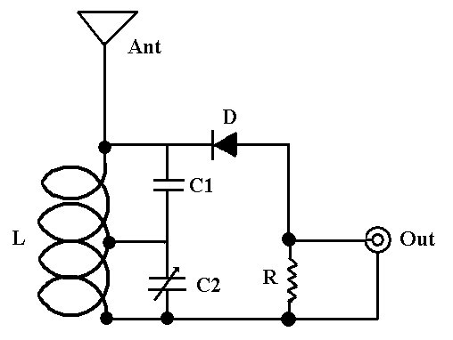
FM Crystal Radio

L - 4 turns #18 copper or silver wire, 12mm inside diameter, tapped at 2.5 turns

Ant - 7 inches of #18 bare copper wire

C1 - 18 pF ceramic capacitor

C2 - 50 pF air variable capacitor (? for 93.5MHz)

D - 1N34 diode or rock crystal

R - 150K resistor

  1. How to tune simplest FM at 93.5MHz radio station by fixed value of C1 (18pF), C2? (any formula would very helpful so that I can tune to any radio station)

  2. Can I use diode 1N4007 instead of 1N34?

\$\endgroup\$
7
  • \$\begingroup\$ C2 is variable, and you probably don't want to fix it, because it compensates for an unknown L. You can estimate L from its geometry, but you're not going to get an accurate inductance. \$\endgroup\$
    – uint128_t
    Commented Feb 19, 2016 at 3:32
  • \$\begingroup\$ @uint128_t updated the question. L is fixed 4 turns #18 copper how about fixed c1,c2 and changing the L value? \$\endgroup\$ Commented Feb 19, 2016 at 3:54
  • 2
    \$\begingroup\$ If using a different diode, you still need one with low forward voltage, as the germanium 1N34 is - so a Schottky, not a 1N4007. Preferably a signal Schottky, not a power Schottky. OTOH, I spent a few hours on Wednesday trying to get this to work, 5 miles from a 10,000 watt FM station (with 1N34) and it was a frustrating experience - not a peep out of the thing. And... L may be fixed, but you have no idea what it actually is, as-wound, since every one will vary a bit. It's an inexact science at best. \$\endgroup\$
    – Ecnerwal
    Commented Feb 19, 2016 at 3:55
  • \$\begingroup\$ @editinit handmade inductors are a bit of an art form. The exact diameter, length and width of every turn can have an impact. You can 'make a guess' based on a nominal inductance value computed from turns#, diameter and coil length, but some 'fine tuning' will most always be necessary. \$\endgroup\$ Commented Feb 19, 2016 at 3:59
  • \$\begingroup\$ Agreed. just wanted to know mathematics behind resonating at 93.5MHz. what values can be variables and what can be fixed. \$\endgroup\$ Commented Feb 19, 2016 at 4:12

1 Answer 1

2
\$\begingroup\$

While the handmade inductor in this project will most definitely vary from any 'nominal' value we can compute (if you have a meter with inductance measuring, that would be very helpful), here are a few calculators/resources which should prove helpful for giving you a 'starting point.'

Keep in mind that a 7" copper wire is far from the resonant length for any FM signal(resonant length for a 93.5MHz quarter-wave antenna would be around 32"), so what you're trying to achieve with the inductor, 2 capacirors & 1 resistor is:

  • A radio receiver (tuner) to select and decode the station you're listening to;
  • An antenna tuner to 'bring down' the impedance of that stubby antenna to a usable value;
  • An impedance matching output to drive your headphlnes, or the input of some form of audio amplifier.
\$\endgroup\$

Your Answer

By clicking “Post Your Answer”, you agree to our terms of service and acknowledge you have read our privacy policy.

Not the answer you're looking for? Browse other questions tagged or ask your own question.