I demonstrated this to a ham club years ago. Thereby hangs a tale...
At the end, I'll explain my possibly simplest FM receiver.
I got called by the FCC to help investigate interference at the local airport. So I loaded up my gear, and went out to talk to the folks. They said the interference was intermittent, but it was people talking and some beeps.
"Got a tape" I ask. "Sure". So they play the tape. Imagine my horror when I hear the repeater that belongs to my ham club! I pulled out my radio, sent the appropriate codes, and shut the repeater down. I told them that I was the president of the ham club, and that the repeater would not go back on the air till the problem was resolved.
So I pulled the repeater and put it on the bench. The PLL, which determines the transmit frequency was hopping between the airport frequency and ours, thousands of times a second! Component drift and some other design difficulties prevented this from being "seen" by the onboard computer and having the transmitter shut down. (Kenwood VHF repeater controller, won't buy again..) The repeater was actually transmitting on BOTH frequencies!
I fixed the component drift issues, retuned the repeater, added a notch filter for the airport frequency on the transmitter output as insurance, and put it back in service.
Back at the club I explained the problem. I got told in no uncertain terms by one of the members that it was IMPOSSIBLE for an AM reciever (aircraft) to get audio from an FM transmitter. I played the tape.. The voice of the person they had recorded was the guy claiming this was IMPOSSIBLE.. (VBG)
So how does this happen? Nothing is ever perfect. The antenna system for our repeater (and any other repeater) has a passband, and the transmitter itself isn't perfectly "flat". So as the carrier is driven to different frequencies by the FM modulation, there is a little bit of AM modulation put on the carrier by the passband of the system. This can also happen on the receiver side.
So I set up a demo. The filters for repeaters are called "cans" because they are large hollow metal cans, internally silver plated, and adjusted by mechanical tuning. These "Cans" are very narrow, High Q filters. I set up a can for our repeater transmit frequency, and added a simple diode and earphone. With careful tuning I was able to demonstrate what was essentially a crystal radio, with only the antenna, can, diode and headphone.
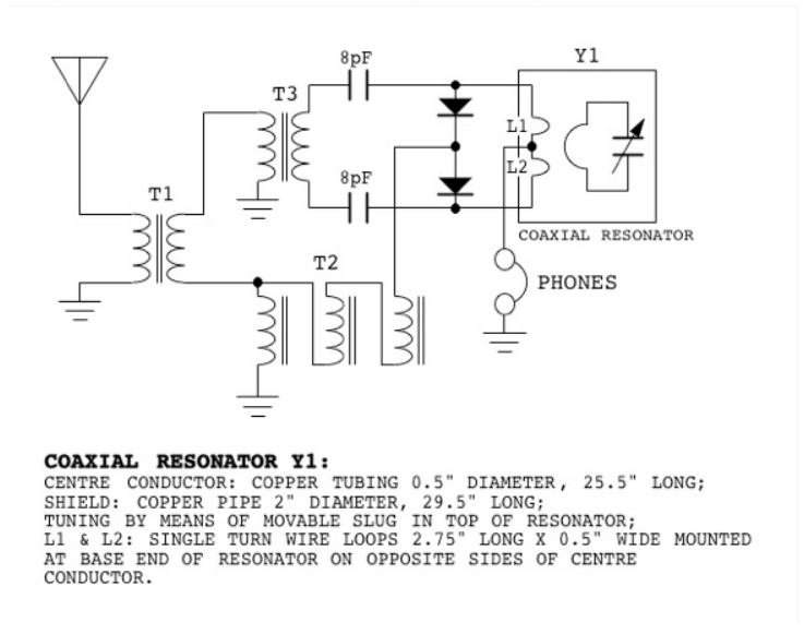
The "simpler" circuit above has seven components counting headphone.
I did it in four. Now it certainly isn't the least expensive circuit, these cans are quite expensive.
All that it takes is to tune the filter such that the FM transmitter carrier frequency is not centered in the filter but is off to the side just a bit, but still within the passband of the filter.
It's called "Slope detection".
http://www.radio-electronics.com/info/rf-technology-design/fm-reception/fm-slope-detector-discriminator.php


