3
\$\begingroup\$

Does anybody know the maximum allowable load capacitance for 74HC04? In the datasheet, nothing is mentioned in the "Limiting values" section. Some of the dynamic characteristics are given for a load capacitance value of 50 pF, but the limiting value is not mentioned. Any ideas?

Abhishek

\$\endgroup\$

3 Answers 3

5
\$\begingroup\$

There really isn't any. The greater the capacitance the slower the output transition, but at least for single outputs, the output can be short-circuited to ground indefinitely. If all outputs are shorted the chip will probably overheat. The slow transition produced by driving a large capacitance can cause big problems if the output is driving other logic unless a Schmitt trigger is used. So how slow a rise or fall time are you willing to accept?

\$\endgroup\$
3
\$\begingroup\$

You can derive a maximum capacitance from thermal considerations (from your datasheet):
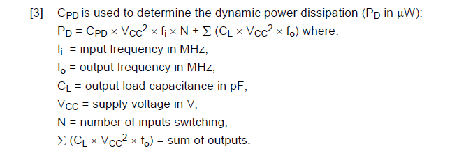
enter image description here

Absolute Maximum allowable dissipation is 500mW at up to 70°C (again, from the datasheet), so maybe we don't go quite that far- say 250mW.

Which gives us \$C_L(\text{max}) \approx \frac{250000}{n\cdot Vcc^2 \cdot f_o}\$ where n is the number of outputs loaded

so if n = 4 and Vcc = 5.1 and fo = 1MHz Cl(max) is about 2.4nF.

Of course the rise and fall times under these conditions will be greatly extended, but the chip should survive, at least for a while. I would be somewhat concerned about long term reliability since there are failure modes that are related to the current passing through internal conductors on the chip.

\$\endgroup\$
2
\$\begingroup\$

Obviously 50 pF is safe, but you can't assume much beyond that.

My take on this is that somewhat larger capacitance isn't going to hurt the device, but the switching time specs are only guaranteed with up to 50 pF on the output.

Basically, these parts aren't intended to drive significant capacitance, so aren't specified that way. If this is really important to you and you want a guaranteed spec from the manufacturer, then you probably have to use a line driver that is intended for such things and specified that way.

\$\endgroup\$
4
  • \$\begingroup\$ I wonder why manufacturers don't more often indicate the degree of tolerance for shorted outputs? There are a lot of devices whose outputs are incapable of sourcing or sinking enough current to cause damage, and even taking into account potential process improvements it would seem helpful to be able to say, "Future versions of the device may source or sink more current, but if they do the pin drivers' ability to withstand current will likewise be increased to match." \$\endgroup\$
    – supercat
    Commented Mar 17, 2016 at 20:48
  • \$\begingroup\$ @supe: Probably because that last sentence is what they aren't willing to promise. \$\endgroup\$ Commented Mar 17, 2016 at 20:56
  • \$\begingroup\$ There's a trade-off between present utility and future enhancements, but there are many cases where a device which can be presumed to have characteristics which present devices do, in practice, have, can be much more useful than one which cannot. Further, specifying such characteristics would not preclude the possibility of the manufacturer introducing an ACME1234A which is similar to the ACME1234 but whose outputs will try to sink 500mA but can only safely dissipate 100mW. \$\endgroup\$
    – supercat
    Commented Mar 17, 2016 at 21:11
  • \$\begingroup\$ Even if the price of the ACME1234 goes up by 25 cents after the introduction of the ACME1234A, it might in some applications still be cheaper than the cost of an ACME1234 plus the circuitry that would be needed to protect it. \$\endgroup\$
    – supercat
    Commented Mar 17, 2016 at 21:12

Your Answer

By clicking “Post Your Answer”, you agree to our terms of service and acknowledge you have read our privacy policy.

Not the answer you're looking for? Browse other questions tagged or ask your own question.