0
\$\begingroup\$

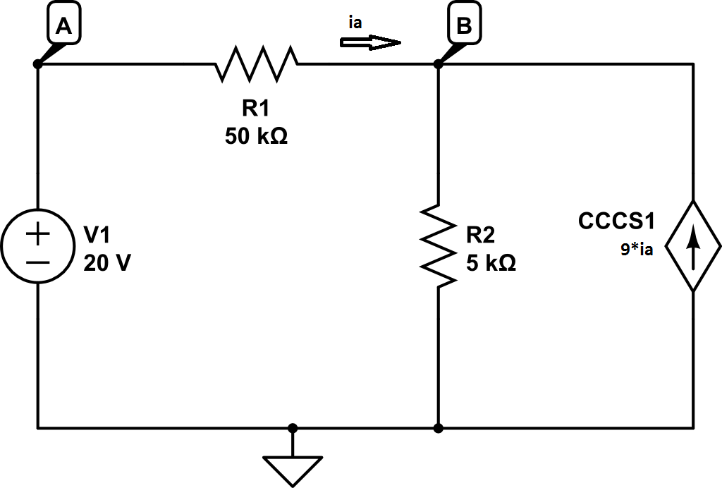
I understand how to find Thevenin equivalents when the are independent sources in the circuit, but once dependent ones are introduced, I get a little nervous.

Here's what I did:

I found the open circuit voltage which is equivalent to voltage Vb relative to ground by doing the node voltage method. I found Vb = 10V.

Then I considered the circuit in the short circuit condition in which an addition connection from node B to ground is made. In this condition, I found the short circuit current to be 4mA.

Thus, the Thevenin equivalent resistor is given by 10V/4mA = 2.5 kOhms. Therefore, the Thevenin equivalent circuit is a 10V voltage source connected to a 2.5 kOhm resistor.

enter image description here

How can I check to see if my answer is correct though?

\$\endgroup\$

2 Answers 2

1
\$\begingroup\$

How can I check to see if my answer is correct though?
The other answer is correct, in that you can use a simulator to check your work.

However, if a simulator is not handy (e.g., as is most often the case on exams), you can analyze the original circuit and your Thevenin model with a load resistor, determine the voltage drop on (or current flow through) the load resistor for both circuits, and compare the results.

If your Thevenin model is correct, you get the same load voltage (or load current) in both the analysis of the original circuit and the analysis of the Thevenin model circuit.

\$\endgroup\$
0
\$\begingroup\$

You can always run simulation of your circuit on simulators like this to verify the values of entities like current in the circuit and output voltage which would remain the same for the original and thevenin equivalent circuit.

\$\endgroup\$

Your Answer

By clicking “Post Your Answer”, you agree to our terms of service and acknowledge you have read our privacy policy.