7
\$\begingroup\$

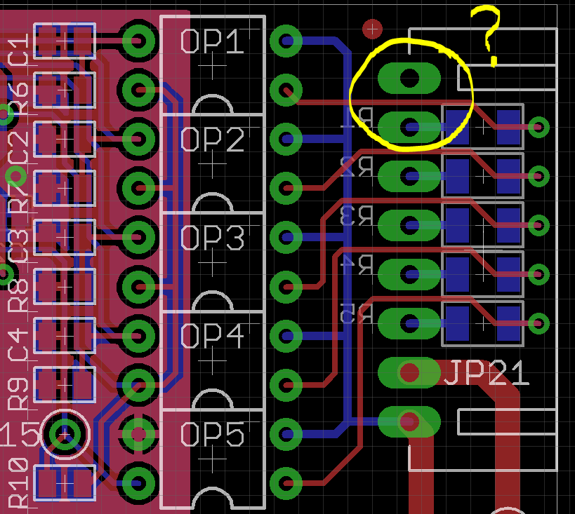
This is a pcb layout where I am converting 220V rms to a DC voltage (for microcontroller). The pcb has severe size constraints. This is one design I could come up with:

Opto coupler

Circuit explanation: Consider the encircled portion. Top pad is not connected. Second one will receive a 220V signal (sometimes). This pin is connected to 270K resistor (blue pads). Other end of resistor goes to opto-coupler (K814P). Same circuit is repeated 5 times. These lines will either be open or will receive 220V rms.

The clearance between pad and trace inside the yellow circle is 12 mils. Is it safe?

\$\endgroup\$
6
  • 3
    \$\begingroup\$ most 1210/2010 resistors cant handle 220V rms with comfortable margins \$\endgroup\$
    – Wesley Lee
    Commented Apr 11, 2016 at 11:07
  • \$\begingroup\$ Can't you use optocouplers in a smaller package (e.g., PC3H4, ACPL-214, PS2805, VOS627)? \$\endgroup\$
    – CL.
    Commented Apr 11, 2016 at 11:37
  • \$\begingroup\$ @CL - Thanks a lot for the tip. I didn't know they existed. Will give them a try. \$\endgroup\$ Commented Apr 11, 2016 at 11:51
  • \$\begingroup\$ You will also need to make sure that the traces are wide enough for the current that the 220V traces will carry. It's possible they're very low-current signals, but seeing as it's a power supply, it seems like the traces should be wider. \$\endgroup\$
    – DerStrom8
    Commented Apr 11, 2016 at 13:11
  • \$\begingroup\$ @wesleyLee - Sorry for late acknowledgement. Thanks a lot for your tip. I had almost missed that part. Can you please suggest some 1206 (preferably) resistors suitable for 220V? I tried digikey but there is no Voltage field. \$\endgroup\$ Commented Apr 11, 2016 at 17:23

1 Answer 1

8
\$\begingroup\$

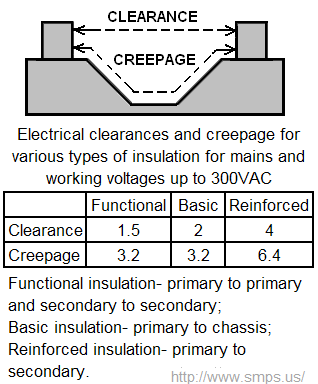
Here's what Creepage and clearance means in UL60950: -

enter image description here

Numbers in millimetres.

"Functional" is the minimal that you are aiming at so, 12 thousandths of an inch is nowhere near enough. Across a plain PCB clearance supersedes creepage distance unless you can force slots into the PCB material.

\$\endgroup\$
3
  • \$\begingroup\$ Yes. In fact, ignoring the traces for the moment, the clearance between the pads of JP21 itself is not sufficient. You simply cannot use a 0.100" header for these kinds of connections. Even a 0.156" header is close, but it can be made to work. Remember, the nominal peak voltage on this kind of circuit is 350 V, and surges can drive it much higher. \$\endgroup\$
    – Dave Tweed
    Commented Apr 11, 2016 at 12:28
  • \$\begingroup\$ Thanks Andy and Dave. Seems like I'll have to go for a re design of that opto coupler part. \$\endgroup\$ Commented Apr 11, 2016 at 13:29
  • \$\begingroup\$ @Whiskeyjack if it gets tight you can always put physical slots in the PCB. \$\endgroup\$
    – Andy aka
    Commented Apr 11, 2016 at 14:04

Your Answer

By clicking “Post Your Answer”, you agree to our terms of service and acknowledge you have read our privacy policy.

Not the answer you're looking for? Browse other questions tagged or ask your own question.