28
\$\begingroup\$

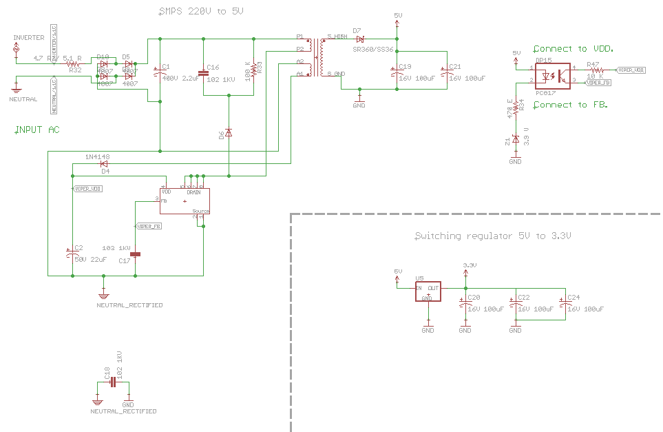
I have a PCB with smps circuit on it 220V to 5V (using Viper22a). Here is the schematic:

Schematics

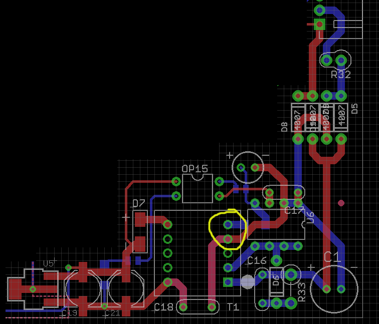
And here is the board layout:

PCB

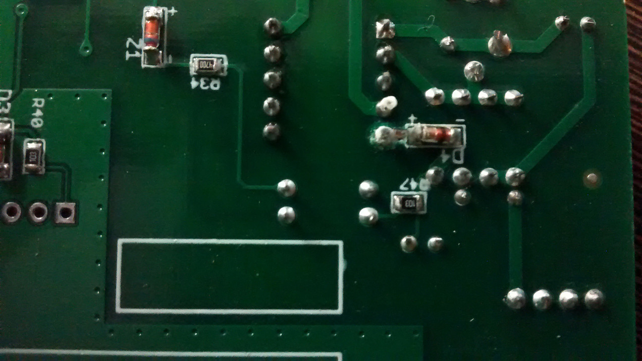
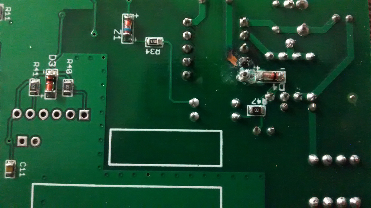
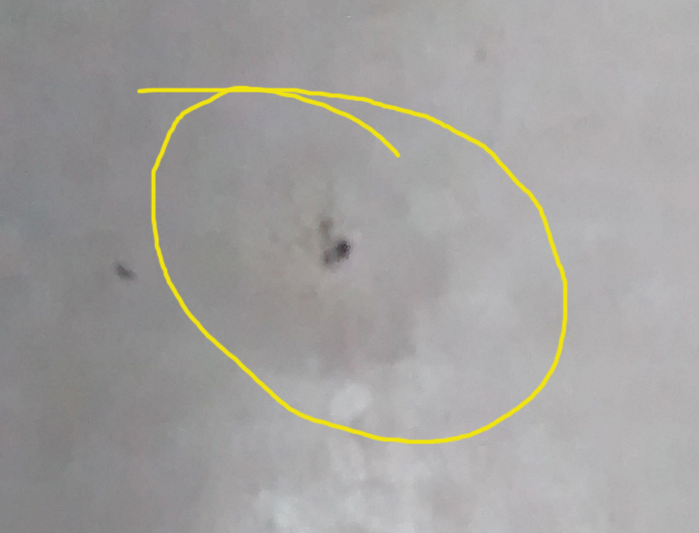
In the yellow circle region, I am seeing some sort of white deposition in a few PCBs(bottom layer). Please see the images below:

1

2

Once scraped off, it takes away the solder mask with it. Deposition starts on both auxiliary winding pins and extends to the diode (bottom layer). Remaining area seems to be unaffected. What could be the reason behind it and how do I avoid such a thing?

I think some sort of chemical reaction is going on probably due to cheap materials used during fabrication or maybe due to improper cleaning of solder flux after soldering. But again, primary winding should be having a higher voltage and hence a better spot for such chemical reactions.

I don't see a temperature rise in that area. It feels cold to the touch.

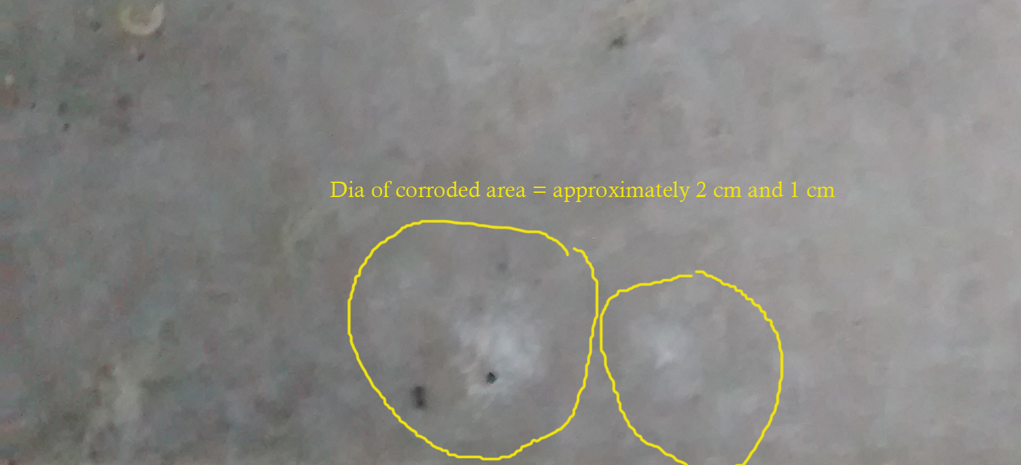
Updates: I had a feeling that this is some sort of chemical reaction. I immediately checked the place where I had placed the PCBs and I found these:

c1

c2

I placed the bare powered PCB on marble thinking it to be insulating. Seems like acid traces from the flux initiated ionic disintegration in the marble first and then DC current pushed the reaction even further. White deposit is deposited calcium it seems. As seen from the marble image, it seems corroded. On touch, it feels rough as if someone dropped a drop of acid on it.

\$\endgroup\$
5
  • \$\begingroup\$ @Nedd - D6 is a part of RCD clamp circuit. That part is alright. The white residual formation is between pin A1, A2 and diode D4. A1 and A2 are the auxiliary winding pins of the transformer. There is nothing sort of short circuit or evaporation. \$\endgroup\$ Commented Apr 20, 2016 at 9:16
  • \$\begingroup\$ Looks like a trace has been blown right off the board too. So the white residue may be PCB material that is being vaporized due to high voltage arcing. In the schematic D6 seems to be the flyback protection diode, but the resistor in series with it looks to be 100k, is that correct? If so, that seems much too high. So if that is the resistor value that might be causing a high voltage sparking condition. \$\endgroup\$
    – Nedd
    Commented Apr 20, 2016 at 9:16
  • \$\begingroup\$ But what is the actual value of R33? If there is some form of continuous arcing on the PCB surface (or internally) this could create a white residue and eventually lead to a catastrophic short. (The "RCD" parts may be OK, but are they working correctly? if there is a high voltage present it just wants to get back to it's local ground.) \$\endgroup\$
    – Nedd
    Commented Apr 20, 2016 at 9:26
  • \$\begingroup\$ R33 = 100K. Seems like this issue was due to marble on which the module was kept. Probably acid traces from flux initiated some sort of reaction in the marble and those ions were getting deposited due to the DC current on those pins. Posting the images. \$\endgroup\$ Commented Apr 20, 2016 at 9:29
  • \$\begingroup\$ I wouldn't think that an acid flux would be used with modern PCB assembly, (though you didn't say who did the assembly) . If there was excess moisture on the boards, or on the marble surface then that may have a chance of causing what you see. Another issue may be what came first, the arc on the board or the potential contamination with the marble surface. In regard to the 100k resistor: Did you assemble these boards, or were they preassembled? I would think that the R33 resistor would be more toward a 100 ohm value. But if your satisfied with the marble surface idea then best of luck. \$\endgroup\$
    – Nedd
    Commented Apr 20, 2016 at 10:13

1 Answer 1

34
\$\begingroup\$

This has a pretty straight forward solution: don't set 300V being switched at 60KHz directly on marble. In fact, you should assume that pretty much anything is NOT safe to put 300V switched at 60KHz on.

Marble is metamorphic rock, structured as different grains from different rocks, with small cracks that will become filled with moisture that conductive ions (calcium is a safe bet) move into from the surrounding minerals. It may seem dry, but unless you recently baked the entire slab in an oven for a couple days or more, there is probably a good deal of moisture that has seeped in just from the ambient humidity.

Before everyone starts measuring their counter tops with an ohmmeter, resistivity is not the thing in play here. Conductive fissures between nuggets of various minerals. Minerals with dielectric coefficients. Sound like anything familiar?

A capacitor, perhaps? Two conductive plates separated by a dielectric... calcium electrolytic moisture in cracks separated by a dielectric.

An interesting property of many minerals is if subjected to a changing electric field, their dielectric constants increase quite dramatically with frequency. You need no low resistance galvanic path to conduct AC. It can pass through dielectric via the polarization and depolarization of the electric dipoles in the material. Simply put, capacitors pass AC, and the more capacitance, the more they pass. Higher dielectric constants mean more capacitance.

This is why marble is conductive to high frequency AC or any changing switching wave form. Exactly like the one that would be seen on the two pins that have the 'deposition.'

Most of the time, this doesn't really matter. And it can be very useful for measuring strain and other effects of marble, though this effect is present in other rock types as well. There is a whole field called Dielectric Spectroscopy that tries to infer various things about a chunk of material by looking at how it's AC impedance varies with frequency. Marble's only goes one way: down (with increasing frequency).

However, 300V from the recitfied 220V line switched at 60KHz is hardly a triviality. Many minerals and ceramics (MnZn ferrite is another example) start becoming more conductive with heating, often exponentially so. I've sent several amps through a ferrite core with less than 30V, you just have to get it hot enough. Well, before it shattered/semisploded. Coupled with the generally terrible thermal conductivity, I'd wager you were having some pretty serious localized heating of the marble table by those two pins.

As for the deposition, given the ions and alkaline nature of deposits in marble, there is probably some small electrochemical something or other going on. You're passing current through weird stuff and making it hot, all sorts of shenanigans could potentially be happening. But it is definitely current driven, there is no issues with flux residue or anything causing this. This is a case of putting your 300V SMPS on stuff you shouldn't, that's all.

The good news is it is specific to the board you tested, I wouldn't worry about any manufacturing issues. This was a very specific instance of 'OOPS!'.

\$\endgroup\$
3
  • 3
    \$\begingroup\$ Glad to know that my thought process was right. It'd had been a nightmare if it was a manufacturing or more importantly circuit design issue (it was highly unlikely but yeah - Murphy's law). Thanks a lot metacollin for this wonderful answer. I had left the circuit ON on marble for 3 days straight. It was some sort of stress test. \$\endgroup\$ Commented Apr 20, 2016 at 12:07
  • \$\begingroup\$ Awesome answer, and I would have upvoted the question just to get this answer closer to the top. Sadly, I had already upvoted the question for another purpose. I bet most electrical engineers have no clue about these things, at least no practical experience, so this is great information. \$\endgroup\$
    – pipe
    Commented Apr 21, 2016 at 5:58
  • \$\begingroup\$ Well, that's a fascinating result. I never would have guessed! \$\endgroup\$
    – Hearth
    Commented Feb 13, 2019 at 17:39

Your Answer

By clicking “Post Your Answer”, you agree to our terms of service and acknowledge you have read our privacy policy.

Not the answer you're looking for? Browse other questions tagged or ask your own question.