I am a computer science student working on a project for my Diploma and I am building a DIY PDU,
I thought building something would be a lot funner then programming a website like 90% of the class
So I have run into a problem with my build,
I have 8 Relays that are controlled by a 74hc595 shift register, this chip is then controlled by an Arduino.
Everything works awesome until i put 230VAC onto the relays and flick all the relays to on (with no load). This is where the problem occurs.
The relays start to tick randomly and stay off !
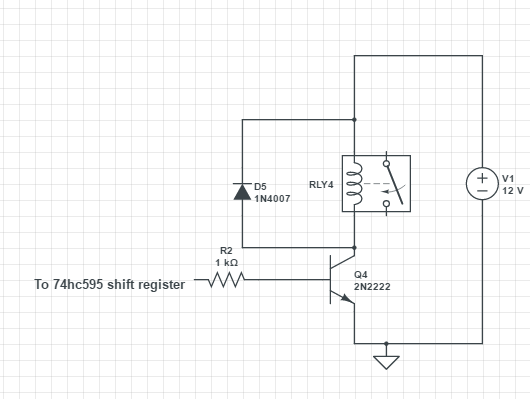
Here is a schematic of the Relay Board
There are 8 of these all going to the 595 chip.
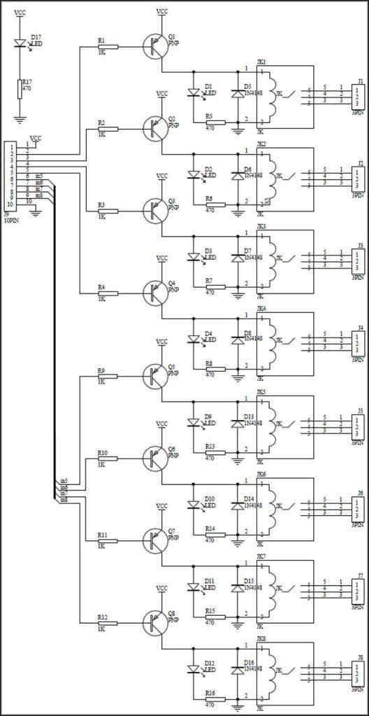
Now I have an 8 Relay Module Board that follows the rougly the same design except it uses PNP transistors and where I used NPN ones
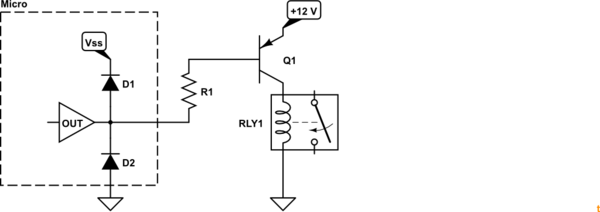
could the different Transistor configuration be somehow effecting the 595 register ! Or am I not using the correct diode configuration ?
NOTES
I have tried and RC snubber between the relay contacts and between the relay + and - of the coil.
When I put a scope between one of the relays coils (NOTE this is a crappy DIY scope from china) and I see I negative voltage just after I put 230VAC through relays ! and then the relays turn off.
When I power the Arduinoo on the Project PSU (using a lm7805 regulators with a .33uf cap on the input and a .1uf cap on the output) the problem is A LOT more apparent !
when I power the Arduino off the USB problem shows up a lot LESS !
Update:
This relay
http://www.gmelectronic.com/relay-with-dc-coil-12v-finder-40-61-9-012-0000-p634-038
This relay
http://www.gmelectronic.com/relay-with-dc-coil-12v-finder-40-61-9-012-0000-p634-038
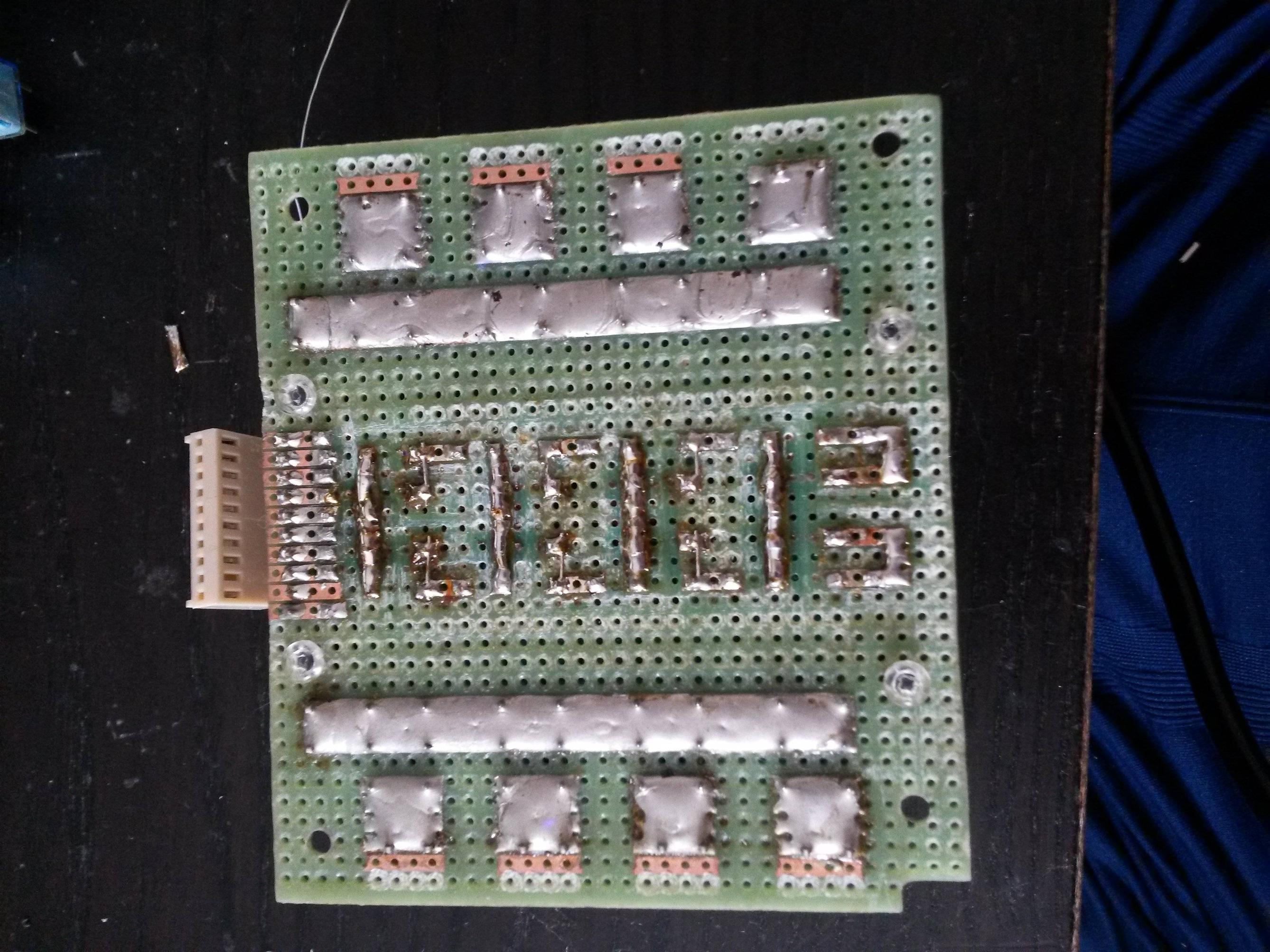
Live is the 2 long strips of solder and the 8 patches of solder at the relay connect points


