1
\$\begingroup\$

I am a computer science student working on a project for my Diploma and I am building a DIY PDU,

I thought building something would be a lot funner then programming a website like 90% of the class

So I have run into a problem with my build,

I have 8 Relays that are controlled by a 74hc595 shift register, this chip is then controlled by an Arduino.

Everything works awesome until i put 230VAC onto the relays and flick all the relays to on (with no load). This is where the problem occurs.

The relays start to tick randomly and stay off !

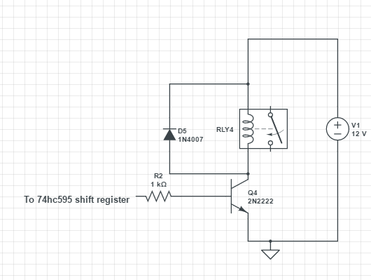
Here is a schematic of the Relay Board

Relay Schematic

There are 8 of these all going to the 595 chip.

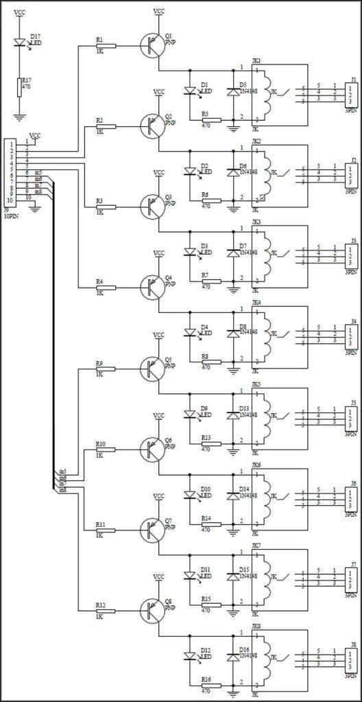
Now I have an 8 Relay Module Board that follows the rougly the same design except it uses PNP transistors and where I used NPN ones

could the different Transistor configuration be somehow effecting the 595 register ! Or am I not using the correct diode configuration ?

enter image description here

NOTES

I have tried and RC snubber between the relay contacts and between the relay + and - of the coil.

When I put a scope between one of the relays coils (NOTE this is a crappy DIY scope from china) and I see I negative voltage just after I put 230VAC through relays ! and then the relays turn off.

When I power the Arduinoo on the Project PSU (using a lm7805 regulators with a .33uf cap on the input and a .1uf cap on the output) the problem is A LOT more apparent !

when I power the Arduino off the USB problem shows up a lot LESS !

Update:

This relay

http://www.gmelectronic.com/relay-with-dc-coil-12v-finder-40-61-9-012-0000-p634-038

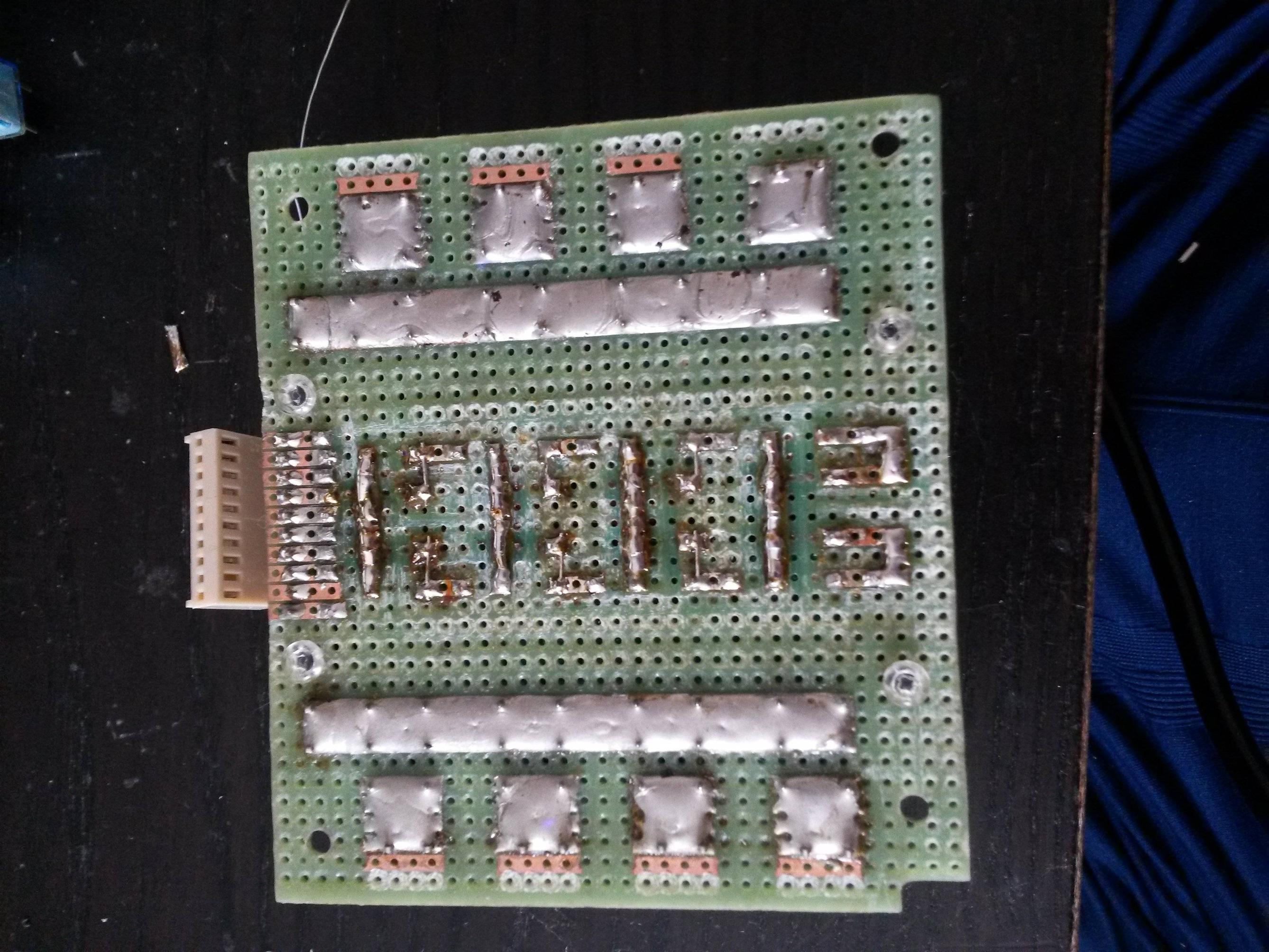
Circuit board: enter image description here


This relay

http://www.gmelectronic.com/relay-with-dc-coil-12v-finder-40-61-9-012-0000-p634-038

Live is the 2 long strips of solder and the 8 patches of solder at the relay connect points

\$\endgroup\$
4
  • \$\begingroup\$ What's the relay you are using? Also show how you connect 230V to it. \$\endgroup\$
    – Eugene Sh.
    Commented May 18, 2016 at 18:15
  • \$\begingroup\$ What is on the other side of those base resistors? A NPN each or just the 74HC595 chip? The latter won't work... \$\endgroup\$
    – Turbo J
    Commented May 18, 2016 at 18:53
  • \$\begingroup\$ If you don't apply 230 to the relays, but try do drive them all anyways, do they start clicking? And are you absolutely sure that your Vdd is 12 volts and not 5? These are, after all, 12VDC relays. \$\endgroup\$ Commented May 18, 2016 at 20:37
  • \$\begingroup\$ No they do not. Only when 230VAC is applied \$\endgroup\$
    – Bskitter
    Commented May 19, 2016 at 13:52

1 Answer 1

3
\$\begingroup\$

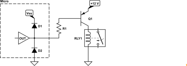
schematic

simulate this circuit – Schematic created using CircuitLab

Figure 1. Using PNP doesn't always work well for level shifting.

If you have done as shown in Figure 1 you may find that the PNP transistor turns on without output from the micro. Q1's emitter-base junction will pass current through R1 and D1, the output protection diode, to the Vss of the micro. This may be enough to cause the relay to pick. You should now see one of the advantages of NPN switching for (voltage) level-switching.

Your options are to go back to NPN, add an NPN 'inverter' in front of the PNP or use an opto-coupler to isolate the two circuits (where micro drives the LED and the transistor is installed in place of Q1). By the sound of things this isn't your only problem but it may be a start.

\$\endgroup\$
1
  • \$\begingroup\$ This is a great way to destroy the MPU, unless all outputs are the OC type. \$\endgroup\$
    – user105652
    Commented May 18, 2016 at 23:02

Your Answer

By clicking “Post Your Answer”, you agree to our terms of service and acknowledge you have read our privacy policy.

Not the answer you're looking for? Browse other questions tagged or ask your own question.