This is a bit of a silly question, and I realize that. It's hard to imagine why one would use relays for this purpose, especially given relay bounce / etc. Nonetheless, it's an interesting exercise, if nothing else.
Any suggestions for how to go about implementing a Muller c-element in relay logic? Ideally, "pure" relay logic, as in no diodes / etc.
(For those who don't know, it's a latch variant. Output goes high when both inputs are high, low when both inputs are low, and stays the same as it was otherwise)
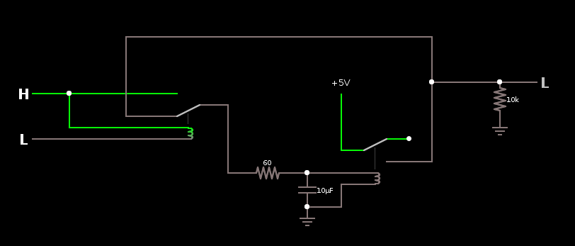
The best I've come up with thus far is this:
It has a few "amusements" though. Let's see:
- R1 is required for the LL(L) -> HL(L) transition, as the first relay must switch before the second
- C1 is required or else the second relay toggles off during the blip when relay one switches during the transition from HH(H) -> LH(H).
- The output glitches slightly (to ~1/2 a volt, in this case, but the numbers are wildly wrong) during a LL(L) -> HL(L) transition if the circuit was previously in a state with output high due to C1 being connected to the output.
- I have no idea how to size R1 and C1 beyond empirically "as small as possible".
- It glitches if the output is too inductive. Rather interestingly, too.
- It might glitch if the input is too inductive.
- It has no snubbing across the coils. (Well, aside from C1)
- It uses 1=high 0=low logic, whereas some things are easier with 1=high 0=floating.
- It uses two relays, whereas there's only one bit of info being stored.


