2
\$\begingroup\$

I'm looking for an IC with the following functional diagram. Basically it's an inverting buffer whose output is open-collector, and that has an enable signal. An equivalent logical circuit would be to replace the notional tristate inverting buffer with a "NOR" gate driving the base of the transistor. Essentially I want the output to unconditionally float when the enable pin is "low". When the enable pin is "high" I want the output to be driven low when the input is driven low and float otherwise.
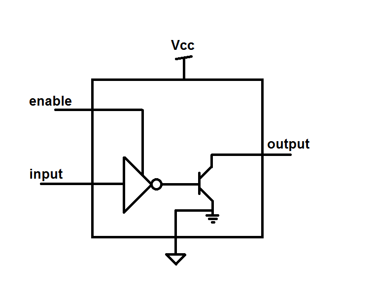
enter image description here

Does anything like that exist? Ideally I'd power it from 1.8V (but I'm flexible on that requirement) and it would come in an SOT-5 package. Suffice it to say this is not for a new design, but rather to put a band-aid on an existing design problem (that I've inherited).

\$\endgroup\$

4 Answers 4

5
\$\begingroup\$

I think you can do this with a single chip if you use a dual NAND gate with open-drain output like 74LVC2G38 (both gates below have open-drain output):

enter image description here

That runs off 1.65 to 3.3 V and it's available in a 2x3 mm 8-pin package, which is pretty close to SOT-23-sized.

\$\endgroup\$
2
\$\begingroup\$

Can you tell us more about what this connects to?

I you have a way of inverting the input, you can use two SOT-23 transistors, such as N-Channel MOSFET.

You might even be able to use 1 MOSFET, with the gate connected to the enable, and the source connected to the input. In this situation the any other devices driving the output low would put the MOSFET in reverse polarity. Pay close attention to datasheet specifications.

\$\endgroup\$
1
\$\begingroup\$

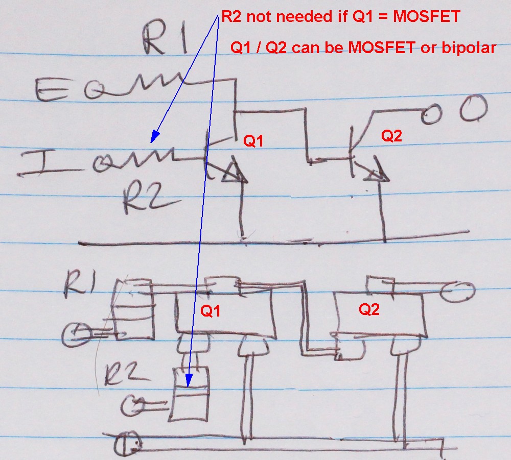
This does what you want.
Either

  • 2 x bipolar transistors, 2 x resistors.

    or

  • 2 x MOSFET, 1 x resistor (or 1 MOSFET, 1 bipolar, 1 resistor)).

    Layout may need work [tm] :-)

enter image description here


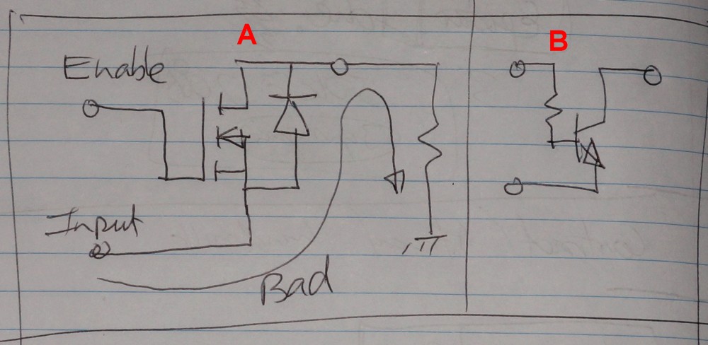
@Michael Pruitt suggested a single MOSFET, as in eg A below.

Both versions shown below need the current sunk by Vin when low to be enough to act as a low for Vout*. eg if Vin is a microcontroller pin rated at 5 m sink and Vout needs a 50 mA sink then neither of these dogs will hunt. [ * I_Vin_capability >=I_Vout ]

But, apart from needing I_Vin = I_Vout as above, there are issues with the body diode conduction path (legal in this case :-) ), as he also adumbrated, when Vin is high and Vout has a load to ground.

The bipolar equivalent in B is less prone to this but whether the CB junction is adequately O/C for you is TBD - probably not as you have a forward biased BC junction fed via R from Enable. This will drive Vout to a Vbe below Venable. If Th output connects to pullup to V>> Venable then this may be OK. .

enter image description here

\$\endgroup\$
1
\$\begingroup\$

A 74HC4053 could provide the desired functionality in a single chip, without wasting static current in resistors, for three inputs if one wanted to use a common active-low enable. Provide the inputs to S1-S3, tie Y1-Y3 to ground, and float Z1-Z3. Connect /E to the desired enable signal.

If one wanted to use a common data input, but three separate active-high enables, connect the data input to /E and the enables to S1-S3. Float Y1-Y3, and tie Z1-Z3 to ground.

If one wants to establish an arbitrary mapping of two inputs to two outputs, including high, low, and high-Z states, a 74HC4052 provides a nice way to do that. Wire the two inputs to the select inputs, the two outputs to the mux outputs, and then wire the mux inputs to +5, ground, or nothing in any desired pattern.

\$\endgroup\$
3
  • \$\begingroup\$ neat little device... so for my equivalent circuit I could just use one channel (say 0) and say S0 = "input", 1Y0 = GND, 1Y1 = OPEN, and /ENABLE = "enable" (where "enable" is active low, otherwise I would just swap 1Y1 and 1Y0) using designators from my circuit above, is that right? \$\endgroup\$
    – vicatcu
    Commented Feb 1, 2012 at 20:55
  • \$\begingroup\$ That's the basic idea. Multiplexers can be amazing little devices. The biggest caveat with the 74HC405x multiplexers (and also the 74HC4066) is that they do have non-trivial "on" resistance, so the multiplexer should be used either to switch things to VDD or ground (or nothing), or else to connect a single input to some other signal. Connecting multiple 74HC405x multiplexers in series can cause signals to degrade to the point of uselessness. \$\endgroup\$
    – supercat
    Commented Feb 1, 2012 at 21:39
  • \$\begingroup\$ Right, beware the on-resistance of HC multiplexers, especially at low supply voltage. But it should also be mentioned that there are much lower-resistance multiplexers available now, many designed for low supply voltages. There are lots of manufacturers, so use Digi-Key's parametric search. \$\endgroup\$
    – markrages
    Commented Feb 2, 2012 at 21:34

Your Answer

By clicking “Post Your Answer”, you agree to our terms of service and acknowledge you have read our privacy policy.

Not the answer you're looking for? Browse other questions tagged or ask your own question.