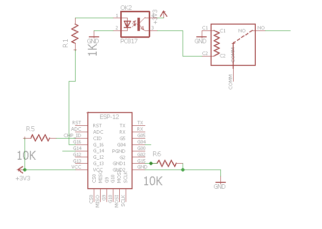
You have the right idea, but your circuit has some problems.
Your 3V relay needs 120mA to operate, but the PC817 optocoupler is only rated for 50mA maximum. Furthermore the optocoupler's CTR (Current Transfer Ratio) could be as low as 50% - requiring up to 240mA LED current to switch 120mA!
So the optocoupler is worse than useless, and since it isn't isolating the relay from your 3.3V power supply there is no reason to have it. You should replace it with an NPN bipolar transistor that can switch 130mA (eg. 2N2222A), or a MOSFET which turns on at 2.5V or less (eg. IRLML2402).
When the relay coil is switched off its inductance will cause a voltage spike as it attempts to keep the current flowing. To prevent damage to the transistor this spike must be suppressed. This is usually done with a diode (eg. 1N4148) connected across the coil in reverse (Cathode to V+).
With these changes the circuit should be safe, provided that you have a good enough isolation barrier between the low and high voltage sides. The most critical point is between the relay's coil connections and COMM terminal, which are only 6mm apart. If you are mounting the relay on a PCB then consider cutting slots between these terminals, to prevent 220VAC from leaking across the board surface.
If the relay is switching an inductive load (eg. motor, transformer) then you may need a snubber across the contacts, to suppress arcing which can damage the contacts and/or cause electrical interference.

