1
\$\begingroup\$

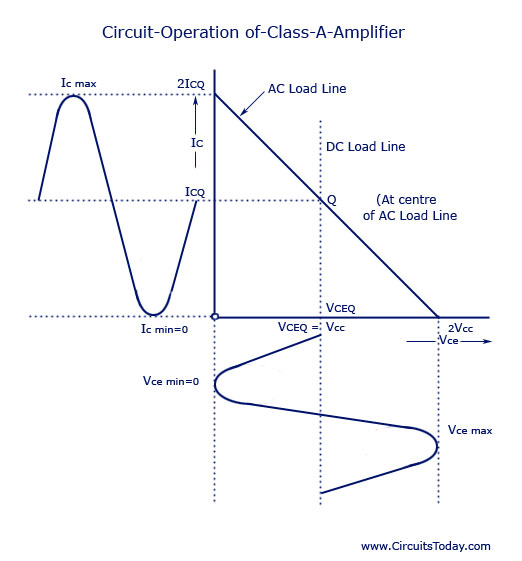
The DC and AC load lines of a transformer coupled Class A amplifier is shown below.

enter image description here

My question:

How can Vce vary from 0 to 2Vcc? In class, I learned that it was due to Lenz Law working in the transformer and a voltage of Vcc being induced to reverse the change in Ic. However, I cannot picture this. Can someone please explain with a diagram of how this comes about in the transformer windings.

\$\endgroup\$
1
  • \$\begingroup\$ > How can Vce vary from 0 to 2Vcc? you are talking about a transformer here. it is an inductor. \$\endgroup\$
    – dannyf
    Commented Jan 21, 2017 at 15:12

2 Answers 2

2
\$\begingroup\$

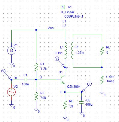
OK, here is a simple schematic of a transformer coupled amplifier;

Circuit

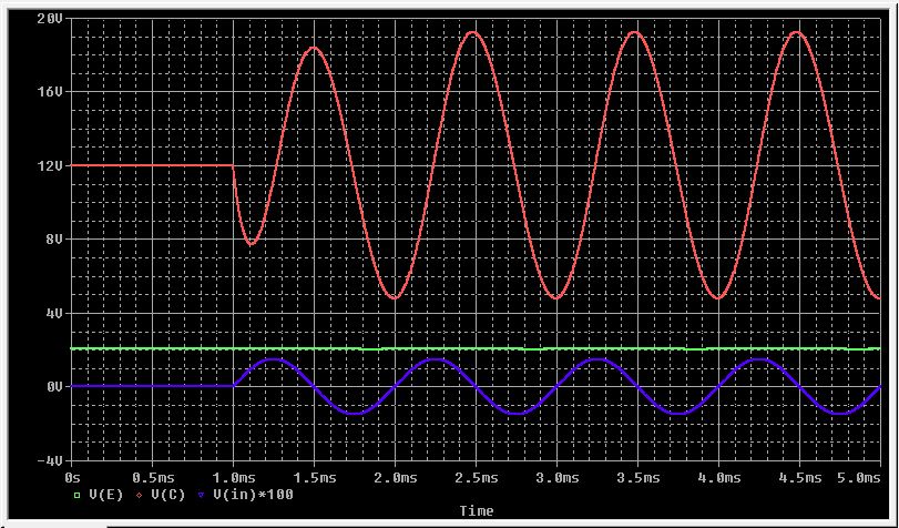
Here are the voltages;

Voltages

Notice before the sin starts the collector is at Vcc, 12V in this case. This is because for DC the inductor is a short. When the sin starts, it can only go as low as VE, which I decided to make about 2V.

The input voltage is multiplied by 100 so it can be seen, otherwise it would look like a flat line at 0V.

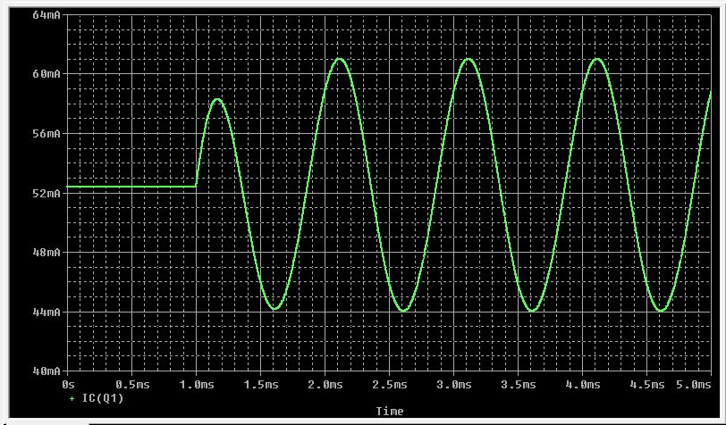
Here is the collector current;

Current

I was trying to get the bias current to be 50mA. This is close enough.

\$\endgroup\$
0
\$\begingroup\$

How can Vce vary from 0 to 2Vcc?

If you have an inductive load in the collector (or drain) of a class A amplifier then, the signal developed across the inductor HAS to have an average value of zero or that magnetic component is going to saturate.

So think about this once again because it is fundamental to your understanding; the average voltage across the magnetic component MUST be zero. Once you have taken this on board it follows that an AC signal superimposed across the magnetic component must not break this rule i.e. its average must be zero.

I'll labour this some more - if the average voltage across the magnetic component were not zero then the current flow, after a short period of time, will be horrendous. It's all embodied in the basic inductor formula: V = L di/dt and, if V is none zero, then di/dt must be finite and therefore a finite di/dt predicts a steadily rising and never ending current of V/L amps.

You will inevitably find that the signal produced swings equally positive above Vcc and negative below Vcc (towards ground). There is no other feasible or practical solution. After all, if you placed an inductor across a power supply, after a short time the supply voltage will have dropped to nearly zero volts with the current being limited only by the inductors winding resistance.

Hence twice Vcc is the theoretical limit.

\$\endgroup\$
1
  • \$\begingroup\$ @Eliza if this answers your question then please consider formally accepting it. If you don't understand something then please ask by raising a comment. \$\endgroup\$
    – Andy aka
    Commented Mar 1, 2017 at 9:38

Your Answer

By clicking “Post Your Answer”, you agree to our terms of service and acknowledge you have read our privacy policy.

Not the answer you're looking for? Browse other questions tagged or ask your own question.