3
\$\begingroup\$

Given the situation where an LED is being used for a status indicator or similar, not toggling quickly.

Which is the best configuration for the IO pin, push pull or open drain? As I see it either will work, and I don't see any benefits to one configuration over the other.

U1 in the following is just representative, not a specific microcontroller.
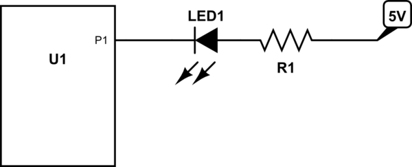
schematic

simulate this circuit – Schematic created using CircuitLab

\$\endgroup\$

3 Answers 3

4
\$\begingroup\$

If U1 is also running from 5 V in your example, then it doesn't matter at all. Either way there will be no current thru the LED when the output is not actively pulling low. It won't matter that it is actively driving high or just open.

There are two cases where it might make a difference:

  1. Not the same power voltage. Open drain outputs can be made to tolerate a higher voltage than the supply voltage without too much burden. For example, you might have a microcontroller running from 3.3 V, but want the LED power to come from a 5 V supply. If the open drain can tolerate at least 5 V when off, then you can connect things just like you show.

    A push-pull output will have some sort of anti-static protection, which usually means a diode from the pin to the positive supply. Generally chips don't like any current thru these diodes during normal operation.

    The LED example with 3.3 V and 5 V is not the best to illustrate this, since 1.7 V across the LED and resistor will cause very little current to flow. However, consider maybe a 6 V supply, or driving a small solenoid or something.

  2. When the pin is also a digital input. Digital inputs are usually intended to be held solidly high or low. In between levels can cause excessive currents to flow, and can even cause oscillations internally. This can be a problem if the open drain driver is off, internally connected to a digital input, and the external circuit allows the voltage to float.

\$\endgroup\$
3
  • \$\begingroup\$ Protection structures in CMOS are usually snapback devices good answer though. \$\endgroup\$
    – RoyC
    Commented Dec 23, 2016 at 12:54
  • \$\begingroup\$ OP must be warned that for most MCUs, the protection diode from the pin to the supply is is not disconnected in high impedance state. Having a MCU able to withstand more than the supply voltage, on any of its pins (including the ones configured in open-collector) is exceptional, and it needs to be checked in the datasheet first. \$\endgroup\$
    – dim
    Commented Dec 23, 2016 at 13:55
  • \$\begingroup\$ @dim: True, but often allowing for higher voltage is the point of providing a open drain output. For example, RA4 on early PIC 16 could usually take over 8 V. \$\endgroup\$ Commented Dec 23, 2016 at 14:02
0
\$\begingroup\$

For one LED, it makes very little difference.

If you have multiple LEDs, it might. If this was just one of many LEDs connected the same way, and you wanted to run them all, you might find that you were getting close to the maximum permitted U1 ground pin current. In that case, taking a few LEDs, connecting them to ground, and driving them from high logic would run the current from the VCC pin.

You might find for your particular choice of U1 that the source and sink currents were different, in which case you might want the higher current capacity.

\$\endgroup\$
3
  • \$\begingroup\$ @RoyC, I believe Neil means if you're running many leds off many pins, then you can use the microcontroller to both source and sink current for them. \$\endgroup\$
    – Colin
    Commented Dec 23, 2016 at 12:18
  • \$\begingroup\$ If you drove them the wrong way up they would. I assumed that as you'd put a microcontroller in your circuit diagram, you'd have enough intelligence to realise that software could be used to invert the drive sense, and would be so obvious to not even warrant a mention. \$\endgroup\$
    – Neil_UK
    Commented Dec 23, 2016 at 12:19
  • \$\begingroup\$ Apologies thought you were talking about connecting the LEDs to the same IO. I was confused because this will make no difference to the open drain/push pull question. \$\endgroup\$
    – RoyC
    Commented Dec 23, 2016 at 12:36
0
\$\begingroup\$

An open-drain pin, when open, will not allow current to flow in either direction. This is safer if it goes to some connector that might get short-circuited, and allows to use a microcontroller with a lower I/O voltage (if it's 5 V tolerant).

If your circuit does not need these features, it does not matter.

\$\endgroup\$

Your Answer

By clicking “Post Your Answer”, you agree to our terms of service and acknowledge you have read our privacy policy.

Not the answer you're looking for? Browse other questions tagged or ask your own question.