Vcc is the power supplied to the Arduino. The ADC does measurements relative to Vcc, so if Vcc changes 10%, the values reported by the ADC will change approximately 10% (the other direction). Vcc depends on what your power supply is supplying, and may not be particularly accurate.
The Arduino's processor chip includes a temperature-compensated bandgap reference that produces a stable 1.1V reference source.If you use this for ADC, then fluctuations in Vcc won't affect the ADC values. The disadvantage is your input voltage needs to be under 1.1V.
The analog/digital converter converts the analog input voltage into a 10-bit value, where 0 represents ground voltage (GND) and 1024 represents the reference voltage or Vcc. (Except 1023 is the highest you can get.) So if you use Vcc, then the meaning of each ADC value depends on what Vcc happens to be. If you use the 1.1V reference, then the ADC values are stable.
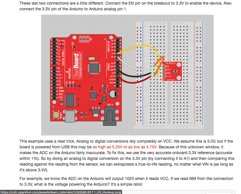
But the circuit you're looking at does things entirely differently. It uses Vcc for the ADC reference voltage. Then they feed the Arduino's 3.3V supply into the ADC and measure its value with the ADC. If you assume the 3.3V supply is accurate, then you can work backwards and figure out Vcc. Finally, you can measure the sensor voltage you want to measure with the ADC, plug in the value you computed for Vcc, and get an accurate sensor reading. This lets you measure values all the way up to Vcc and correct for variations in Vcc.
The 3.3V supply is generated by a linear regulator on the Arduino board, which is supposed to be accurate to 1%. So if you assume you don't have any voltage drop between the regulator and the Arduino, and you assume that Vcc stays constant while you do this, then everything works well.
The math: Suppose your first measurement (of 3.3V) is \$n_1\$ and your second measurement (of the sensor) is \$n_2\$. We have
\$3.3V = n_1 * \frac {V_{cc}}{1024}\$
\$V_{sensor} = n_2 * \frac {V_{cc}}{1024}
\$
We can cancel out \$V_{cc}\$, eliminating the inaccuracy from its value:
\$V_{sensor} = 3.3V * \frac{n_2}{n_1}\$

