1
\$\begingroup\$

In this age of questing for ever-more-efficient circuit designs, I have been presented with an anachronistic design problem: I need to keep a roughly constant load on a steam-powered turbine generator. So I am looking for a linear regulator circuit that can dissipate slightly over 50W when all of the system electrical loads are switched off. And this is in a hostile environment: It's attached to a model steam locomotive, so exposed to relatively high ambient temperatures.

I presume such circuits were once commonplace (for example in early automotive applications... or in real steam locomotives!) but I am not finding a lot of reference information on them online. Can anyone recommend a good design resource for such circuits? And perhaps an existing linear regulator part with a scheme for dissipating that much power in a high-temperature environment?

The raw output of the generator is specified to be 3-phase AC, 0-12V (RMS? Peak-to-peak?) and 0-4.2A.

\$\endgroup\$
7
  • \$\begingroup\$ Is the main load connected to the 3-phase AC output directly or through a rectifier? \$\endgroup\$ Commented Mar 15, 2012 at 19:42
  • 2
    \$\begingroup\$ Not an EE comment, but why you need to do this may inform the best answer. Is the requirement here to burn up the extra power because it is surplus, and the voltage rises with reduces electrical load? Or is the whole point to test the turbine under high load? If the former, I was wondering whether you could mechanically regulate the head pressure in conjunction with the electrical regulation solutions presented? \$\endgroup\$
    – Tevo D
    Commented Mar 15, 2012 at 20:30
  • \$\begingroup\$ @NickAlexeev: The load consists primarily of 12 6V lamps and the power is converted to DC by a rectifier. \$\endgroup\$ Commented Mar 15, 2012 at 21:07
  • \$\begingroup\$ @TevoD: The goal is to allow the turbine's input pressure to be set once and then mostly forgotten. Without some form of dissipating regulator, when the lights are switched off the generator unloads and the turbine overspeeds. \$\endgroup\$ Commented Mar 15, 2012 at 21:10
  • \$\begingroup\$ Wouldn't the historically accurate approach be to use a fly-ball governor driving a pressure relief? </irony> \$\endgroup\$
    – JRobert
    Commented Mar 19, 2012 at 0:41

3 Answers 3

3
\$\begingroup\$

Bridge rectify the AC and smooth (smoothing almost optional) supply a resistive load that will provide somewhat more than the rated power
eg ~= R <= V^2/P <= 144/50 <= 2.88 ohm
So a say 2 ohm 100 W resistor.
This could be eg a coil of suitably thick Nichome wire which is vailable from industrial suppliers.

Then PWM this with a transistor (MOSFET liable to be easiest) and vary the PWM duty cycle. PWM duty cycle can be automatically adjusted to act as a regulator. Circuit can be provided but that may be enough.

I did essentially this some years back to provide 500 Watt+ loads for exercise machines. Works well. I used ~= 20 kHz PWM mainly to get PWM rate above audible so "singing" alternator was not objectionable. In your case a very low PWM frequency may be acceptable - essentially a subsonic buzz.

\$\endgroup\$
3
  • \$\begingroup\$ So basically a switching power supply design? This sounds do-able, but I can't help thinking there must be a more primitive circuit that could do the job. \$\endgroup\$ Commented Mar 15, 2012 at 21:36
  • \$\begingroup\$ @KaelinColclasure - you want a variable device. A PWMd resistor places the energy in a resistor. You could relay switch resistors or use a linear regulator where heat was dissipated in a transistor. The circuit can be as 'primitive' as a 555 driving the FET. I'm not sure that more primitive than that is a bonus. You could use polyfuses or NTC thermistors BUT knee sharpness is poor. You could use VERY BIG [tm] zener diode(s). I think a PWM loaded resistor sounds a fairly good idea. Bulletproofness can be made good and it comes close to what I'd sometimes call "steam powered" :-) \$\endgroup\$
    – Russell McMahon
    Commented Mar 15, 2012 at 22:24
  • \$\begingroup\$ Not really a switching power supply, since the goal here is simply to waste power. See link in my edited post above. \$\endgroup\$
    – supercat
    Commented Mar 15, 2012 at 22:27
1
\$\begingroup\$

If your goal is to waste 50 watts worth of steam, your best bet is probably to PWM a resistor. If, however, your actual goal is to avoid letting out lots of steam when there isn't a huge demand for electricity, then what you really need is a switching power supply whose feedback loop operates effectively backward from a more typical one, such that it will draw maximum current under conditions of minimum load. Because of the odd feedback response in the system, it will almost certainly be necessary to use a two-stage design: stage one will use the generator to charge a cap whose voltage may vary widely (probably by a factor of at least 2:1). Stage two will feed that cap into a more conventional switcher to yield a regulated output. Note that if the load can quickly increase from e.g. 1 watt to 50 watts, it may be necessary for the first stage of the supply to shut down for a significant fraction of a second while the generator speeds up enough to supply 50 watts; the cap must store enough energy to deal with that. Note that trying to draw current from the generator when it's significantly below the necessary speed will increase the amount of time the cap will have to supply power, and in most cases increase the total energy the cap has to supply.

BTW, a simple PWM/resistor approach is shown here. Not much to it. The variable voltage, series resistor, and cap are used to model the generator (here, scaled to produce 10-75mA). When less current is drawn than what's needed to maintain equilibrium, the generator will speed up and the voltage will increase; when more current is drawn, it will decrease. The latch will output high when the input is 2.5 volts or above; since I'm using a 4:1 voltage divider, it will detect whether the cap is above or below ten volts. When the cap is above ten volts, the transistor switches in a resistor that poses roughly a 100mA load.

Note that changing the input current to this circuit (meaning the difference between the current that must be drawn from the generator, and the current that other stuff uses) will only marginally affect the voltage on the 1uF cap (meaning it will only marginally affect motor speed). In practice, generator speed variations would be nowhere near as severe as shown here (the generator's inertia would behave like a much larger cap) but I chose a small cap so as to show how the PWM works.

\$\endgroup\$
3
  • \$\begingroup\$ As this is for a model steam locomotive, the goal is to keep the design as simple and bullet-proof as possible. When I raised the possibility of regulating the steam pressure with a closed-loop solenoid mechanism the response was simply: No. The operator adjusts a "throttle" attached to the line feeding the turbine to achieve a desired set-point (I believe based on the sound!) and that is considered a feature. :-) \$\endgroup\$ Commented Mar 15, 2012 at 21:19
  • \$\begingroup\$ To clarify (I hope), the pressure of the steam input to the turbine is set once by the operator. With no output regulation, the speed of the turbine varies as the electrical load varies. What is desired is that the speed of the turbine remain constant without adjusting the input pressure. So, presenting the generator with a constant load seems to be the only recourse. \$\endgroup\$ Commented Mar 15, 2012 at 21:41
  • \$\begingroup\$ If steam coming out of the turbine supplies draft for the heat source, you could probably achieve somewhat efficient closed-loop control without needing any valves (the turbine would run slower, and produce less draft, when loading was light). Note that if the electronics attempt to regulate the turbine voltage, that will probably work pretty well to regulate its speed, independent of pressure. \$\endgroup\$
    – supercat
    Commented Mar 15, 2012 at 22:06
1
\$\begingroup\$

If I understand your question correctly, you need a ballast circuit. It would be connected in parallel with the main load. It would shunt the excessive power, when the load demands are low.

Resistor w/ PWM

PWM controlled resistor is a good approach, especially if your system already has a controller to generate PWM with. This approach was described in detail in previous posts.

Linear ballast circuits

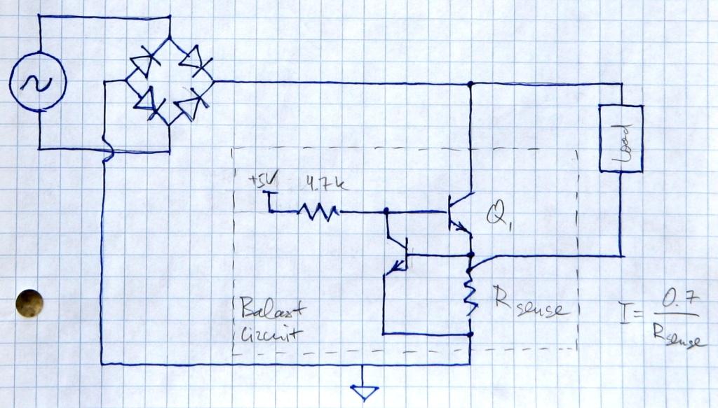
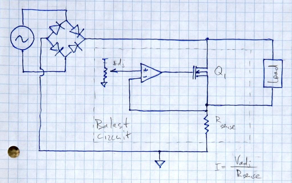
Here are 2 circuits (which are variations of constant current circuits). They regulates current rather than power, so it could be only an approximate answer to your question. These circuits try to maintain a constant current through \$R_{sense}\$. Load and the shunt transistor \$Q_1\$ are connected in parallel, and they share the sense resistor \$R_{sense}\$. If the load doesn’t pull enough current, shunt transistor starts to \$Q_1\$ conduct more current. Power is dissipated on \$Q_1\$ and (to a smaller extent) on \$R_{sense}\$.

OpAmp ballast circuit

enter image description here

BJT ballast circuit

fewer components enter image description here

\$\endgroup\$
8
  • \$\begingroup\$ Are you sure this is working? Lets look at the opamp ballast circuit. When the load doesnt draw enough current, Q1 will conduct. But wouldnt the current through the load drop, until all of the current flows through Q1? I mean when Q1 conducts it is almost shorted, why should the current flow through the load anymore? \$\endgroup\$
    – PetPaulsen
    Commented Mar 15, 2012 at 23:17
  • \$\begingroup\$ I don't think a constant current circuit is really appropriate here; even though the goal is to minimize the extent to which changes in demand affect the current seen by the generator, I would expect that the speed of a turbine driving a constant-current load would vary greatly with steam pressure. If an increase in turbine speed does not cause an increase in current draw, speed regulation is apt to be poor. \$\endgroup\$
    – supercat
    Commented Mar 15, 2012 at 23:24
  • \$\begingroup\$ @PetPaulsen Feedback should take care of this. It's easier to answer your question on the OpAmp circuit. Suppose, ballast draws all of the prescribed current I. Ibalast = Iset. Q1 conducts, but it's not shorted. It operates in the linear region (this is a linear circuit, not a switch). We add load. There will be some current through the load Iload, which will be added to the shunt current. Now, the current through the sense resistor is greater than prescribed. Ibalast+Iload>Iset. Feedback will make Q1 conduct less. \$\endgroup\$ Commented Mar 15, 2012 at 23:28
  • \$\begingroup\$ @Nick Alexeev - I thought of Q1 as a switch. Now I got it, thank you! \$\endgroup\$
    – PetPaulsen
    Commented Mar 15, 2012 at 23:35
  • \$\begingroup\$ I haven't really seen transistors used to dissipate power before. Are there really power transistors capable of continuously dissipating 50W? \$\endgroup\$ Commented Mar 16, 2012 at 15:21

Your Answer

By clicking “Post Your Answer”, you agree to our terms of service and acknowledge you have read our privacy policy.

Not the answer you're looking for? Browse other questions tagged or ask your own question.