You use the term 'trace width' as if it's some sort of universal constant. It's not. Unless a trace has to be a specific width (for impedance control), it's generally as narrow as it can be limited by the necessity to carry current, not drop too much voltage, or be printable within the PCB fab tolerances that you've chosen to afford.
The requirements for the spokes of a thermal relief are different, but they too will be limited at the small feature end by the pcb fab tolerances.
... (assuming current will take a direct path, using only one spoke) ... (assuming the current will only flow to max of a trace, then find another route)?
Neither. You would need to be at high microwave frequencies for for 'direct path, other path' geometry to be significant. The current doesn't 'know' what the max of a trace is, it doesn't use one up to the max and then find another route.
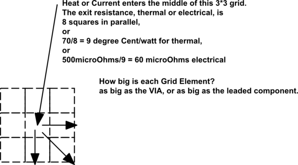
What the current will do is use all parallel paths from pad to ground pour in the ratio of their impedances. The resistive part will tend to be more or less balanced by geometry, and at modest frequencies, say below 3GHz, the inductive difference will be negligible as well. That means that, as a first approximation, the current will split more or less equally through all spokes.

