3
\$\begingroup\$

I plan to use P-MOSFETs (SI7463) as high side load switches, with a slight soft-start (to be tested and tweaked after PCBs are made).

I'd like to parallel them in order to make the equivalent Rds-on lower, but I can't find simple straightforward recommendations on how to do so.

I'd imagine that due to their positive temperature coefficient they will "automatically" share current "equally", however, I've seen some parallel applications in which a small series resistor is recommended (which defeats the purpose for me).

Does a simple implementation like this lack anything?

The load are LED Panels, up to 8A total. Switching frequency is maybe once or twice a day (10uHz? :D ).

With an advertised Rds-on of ~0.01R and 8A, power dissipation would be 0.6W. Junction to ambient on a 1x1" FR-4 board is about 52C/W typical, so 31C temp rise.

Adding an extra FET would be an easy and cheap way of halving the power dissipation and enlarging the effective dissipation area.
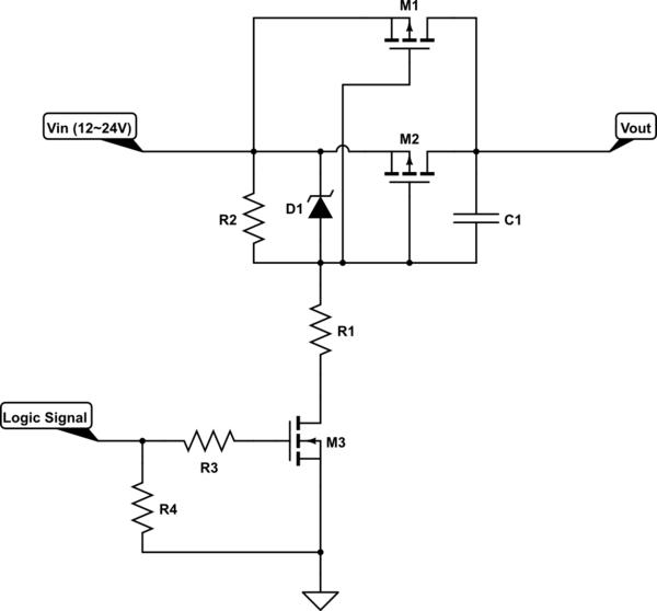
schematic

simulate this circuit – Schematic created using CircuitLab

Follow up:

I ended up following Trevors advice and using a single more expensive device with lower Rds-on (BSC030P03NS3). To the touch, it feels like the traces around the device heat up more than the device itself (4 layers, 10mm wide, 35um thickness on external and 17um on internal). (They are probably the same temperature and the copper feels hotter than the plastic). It works fine without heatsinks cause the avg temp over time is much lower than the peak (8 Amps).

\$\endgroup\$
6
  • 1
    \$\begingroup\$ Individual gate resistors! See: electronics.stackexchange.com/questions/274557/parallel-mosfets/… \$\endgroup\$
    – winny
    Commented Mar 13, 2017 at 18:26
  • \$\begingroup\$ @winny -- thats a nice post, I didnt see it. My application requires very seldom switching (once or twice a day). But individual gate resistors are cheap to add, so why not. \$\endgroup\$
    – Wesley Lee
    Commented Mar 13, 2017 at 18:36
  • \$\begingroup\$ You can still destroy them in just one turn on or off if you have oscillations. That's what happened in my circuit. \$\endgroup\$
    – winny
    Commented Mar 13, 2017 at 18:55
  • 2
    \$\begingroup\$ "Adding an extra FET would be an easy and cheap way of halving the power dissipation and enlarging the effective dissipation area." First step should always be to see if you can find a better device. The costs of a better one may well out-weight the extra costs of two devices plus all the heat-sinks and will improve reliability. \$\endgroup\$
    – Trevor_G
    Commented Mar 13, 2017 at 19:01
  • \$\begingroup\$ You can also significantly drop that 52C/W typical on the PCB by using larger PCB pads and a copper filled, thermally coupled, clear space around the device. \$\endgroup\$
    – Trevor_G
    Commented Mar 13, 2017 at 19:32

2 Answers 2

1
\$\begingroup\$

Another issue you need to consider is the thermal effects of the heat-sink...

Depending on the airflow and the geometry of the heat-sink, one end may be hotter than the other. Further, if, for example, there are three MOSFETS in a line, the central one can be considerably hotter than the other two.

In addition, there are mechanical considerations that need to be accounted for.

Can you guarantee three or more MOSFETS soldered into a board will all have intimate thermal contact with the heat-sink if it is attached later.

If the components are surface mount, will the thermal expansion of the heat-sink cause undue stress and or failure of the solder joints.

\$\endgroup\$
3
  • \$\begingroup\$ At 0.5W and 52C/W with 1x1" FR-4 I was planning not to use heatsinks. I'd use 2 devices, not 3. I was considering your suggestion of switching to a better device. If we consider same cost for 2 in parallel and a single device, could you explain why 2 devices in parallel are less reliable? \$\endgroup\$
    – Wesley Lee
    Commented Mar 13, 2017 at 19:22
  • 1
    \$\begingroup\$ Every device has a failure rate... say your MOSFET has a failure rate of 1:1000. If you have two of them you ADD those numbers. so.. two devices = 2:1000. That is you reduce the reliability of the switch by half. (Assuming the same wattage per switch of course) \$\endgroup\$
    – Trevor_G
    Commented Mar 13, 2017 at 19:25
  • 1
    \$\begingroup\$ I ended up switching the two FETs in parallel for a single device with lower Rds-on. Thanks for your input :) \$\endgroup\$
    – Wesley Lee
    Commented Mar 15, 2017 at 18:51
2
\$\begingroup\$

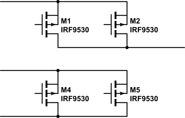
Your FETs have low RdsON, so don't forget to equalize length of copper traces. I have illustrated this:

schematic

simulate this circuit – Schematic created using CircuitLab

Notice on top schematic, both FETs have identical "wire" length. In bottom schematic, the one on the right has longer "wires".

If you use 4 layer board, remember copper thickness is different between layers...

\$\endgroup\$
2
  • \$\begingroup\$ Hadn't thought about the effect of trace/polygon length/distance. Nice reminder. \$\endgroup\$
    – Wesley Lee
    Commented Mar 13, 2017 at 18:46
  • \$\begingroup\$ You could also use lower RdsON NMOS and switch the GND... \$\endgroup\$
    – bobflux
    Commented Mar 13, 2017 at 18:54

Your Answer

By clicking “Post Your Answer”, you agree to our terms of service and acknowledge you have read our privacy policy.

Not the answer you're looking for? Browse other questions tagged or ask your own question.