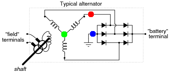
Lets say we have a typical automotive alternator (as shown in the picture) and we are measuring voltage between red and blue dot. How do we calculate voltage between green and red dot? 
-
\$\begingroup\$ When the diode array isn't broken, all the "three red dots" have the same voltage, just shifted by 120° phase angle each, against both the green dot and the blue dot. That means green dot and blue dot can be thought connected without any current flowing. \$\endgroup\$– JankaCommented Mar 26, 2017 at 13:01
-
1\$\begingroup\$ That is certainly not true. Voltage between green and red dot (phase voltage) is AC voltage, thus positive and negative, while voltage between red and blue dot is always positive (if we ignore diode voltage drop). Measured on real system. \$\endgroup\$– jurijCommented Mar 26, 2017 at 13:04
-
\$\begingroup\$ @Janka: Connecting the green dot with the blue dot connects the negative-side diodes directly across the source L-N. That would probably make the voltage between the red and green dots to drop to zero briefly and then become the same as the voltage between the red dot and the blue dot after the negative side diodes are vaporized. \$\endgroup\$– user80875Commented Mar 26, 2017 at 15:33
-
1\$\begingroup\$ @Charles: I know that, that's why I wrote: "Can be thought". When the diode is conducting, the voltage between red and blue is zero (ignoring the diode voltage drop). So there is no way to tell the voltage between red and green from that. So the only relevant case is the other one, when the diode is non-conducting. Then, blue and green could be connected (no current flowing) and the voltage between red and green is the same as between red and blue (by definition). Whether this applies to reality depends on the star being symetrically loaded, which it is when all the diodes are ok. \$\endgroup\$– JankaCommented Mar 26, 2017 at 18:01
3 Answers
Completely revised answer...
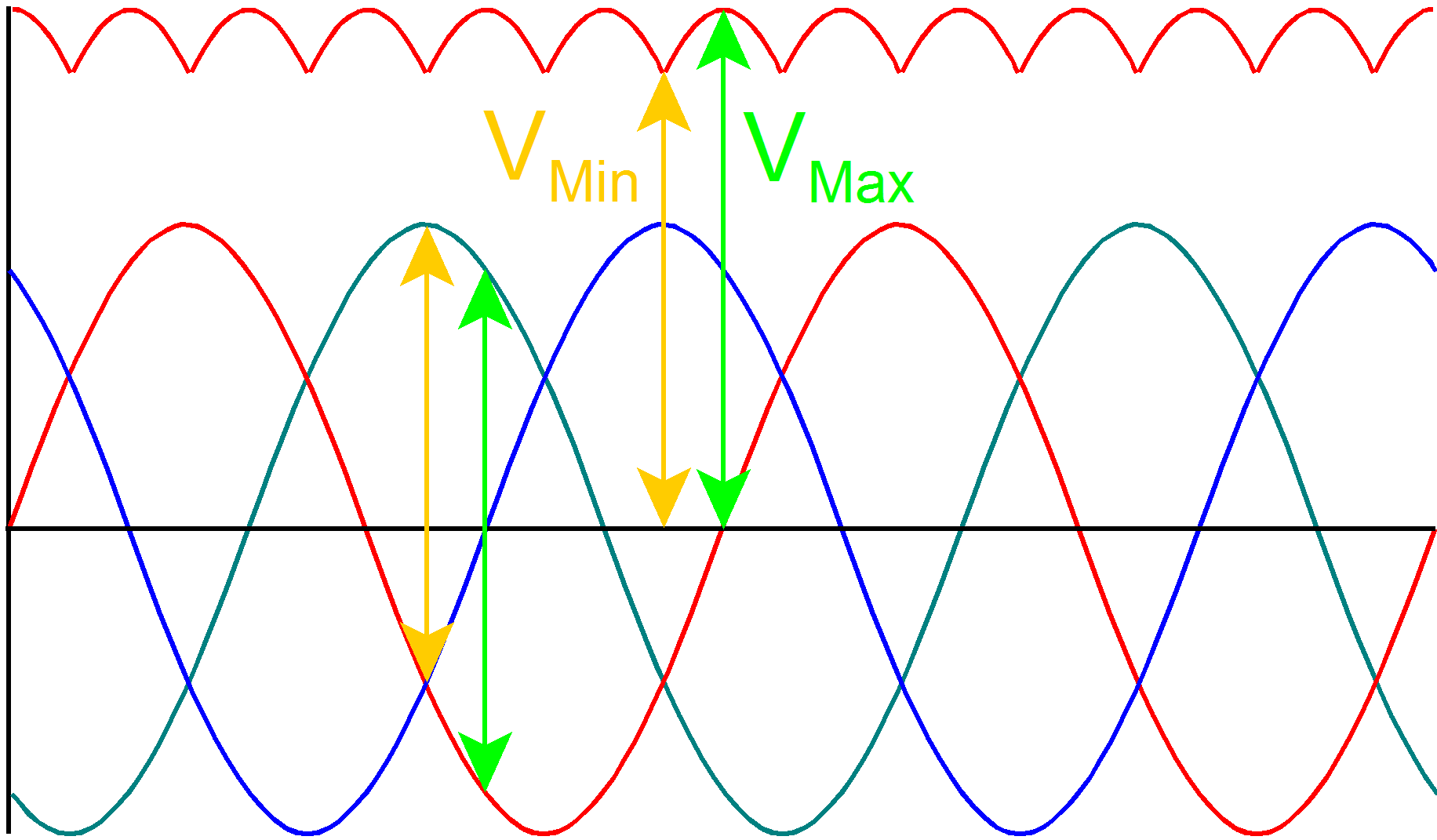
If the alternator produces 9V peak sine waves. Your Red Dot to Green Dot voltage will vary from -9V to 9V.
\$V_{Red} = 9 sin (\omega t) V \$
\$V_{Green} = 9 sin (\omega t\ -\ 120^{\circ}) V \$
\$V_{Blue} = 9 sin (\omega t\ +\ 120^{\circ}) V \$
$$V_{Min} = 9 sin (90^{\circ}) - 9 sin (90^{\circ} +\ 120^{\circ}) - 2 \times 0.7V = 12.1V$$
$$V_{Max} = 9 sin (120^{\circ}) - 9 sin (120^{\circ} +\ 120^{\circ}) - 2 \times 0.7V = 14.19V$$
The actual voltage seen by the battery will be line-to-line voltage across two phases minus the diode voltages.
\$V_{Line} = \sqrt {3}\ V_{Phase} = \sqrt {3} \times 9V = 15.59V\$.
\$V_{Bat} = V_{Line} - V_{diodes} = 15.59V - 1.4V = 14.19V\$.
\$I_{Bat} = \frac {V_{Bat}} {R} = \frac {14.19V} {100\Omega} = 141.9mA\$.
Maximum Power at Resistor:
$$ P = \frac {V_{Bat}^2}{R} = \frac {(14.19V)^2}{100\Omega} = 2.01W $$
Three-phase Power:
$$ P = \sqrt {3}\ V_{Bat}\ I_{Line}\ cos \theta = \sqrt {3} \times 14.19V \times 141.9mA \times 1 = 3.487W$$
The Three-phase Power calculation is wrong because of the action of the diodes.
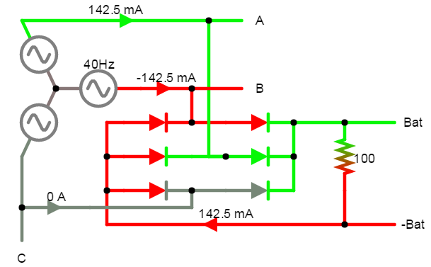
Only two sets are on at the same time as shown by the drawing. This also means there will be current flowing in the neutral.
 Single-phase Power with Line voltages:
$$ P = V_{Bat}\ I_{Line}\ cos \theta = 14.19V \times 141.9mA \times 1 = 2.01W$$
This agrees with the load calculation.
Single-phase Power with Phase voltages: $$ P = \sqrt {3}\ V_{Phase}\ I_{Phase}\ cos \theta = \sqrt {3} \times (9V - 0.7V) \times 141.9mA \times 1 = 2.04W$$ Again, this agrees. Because of the \$\sqrt {3} \$, I'd go with line voltages.
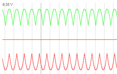
The action of the diodes also means the Green and Blue dots will NOT be at the same potential. Image shows +Bat varying from 8.35V to 3.86V, while -Bat varies from -3.86V to -8.35V. This brings us back to the \$V_{Min}\$ calculation.
$$V_{Min} = 8.35V - (-3.86V) = 12.21V $$
$$V_{Min} = 9 sin (90^{\circ}) - 9 sin (90^{\circ} +\ 120^{\circ}) - 2 \times 0.7V = 12.1V$$
Your Green Dot will be at 0V and the Blue Dot to Green Dot voltage will vary from -3.86V to -8.35V.
Minimum Power: $$ P = \frac {V_{Bat}^2}{R} = \frac {(12.1V)^2}{100\Omega} = 1.46W $$
Numbers should scale to real world.
To calculate phase voltage:
- Measure \$V_{Bat_{Min}}\$.
- Calculate \$V_{Phase} = (V_{Bat_{Min}}\ +\ 1.4V) \times \frac {2}{3}\$.
To calculate power (Max or Min):
- Measure \$V_{Bat_{Min}}\$.
- Measure \$I_{Bat_{Min}}\$.
- \$P = V_{Bat_{Min}} \ I_{Bat_{Min}}\$
- Repeat using Max quantities.
-
\$\begingroup\$ Thanks for the answer. Let's say we don't operate with actual voltages, since they are measured anyway. Let's just call them voltages A, B, and C (imagine each coil has a separated red dot at the output). All of these three voltages are measured to the rectified ground (blue dot). How can we calculate power of the AC part? We are also measuring current through each phase, of course. Let's also ignore voltage drop on diodes. Thanks. \$\endgroup\$– jurijCommented Mar 28, 2017 at 17:58
-
\$\begingroup\$ It's a three-phase system, apply three-phase power. \$\endgroup\$ Commented Mar 28, 2017 at 20:09
-
\$\begingroup\$ Well, true, but in order to calculate power, we would need to measure voltage across the coils (from red point to green point for each of the three coils). Then, we could use formula P (power) = sqrt(3) * U (voltage across coil) * I (current through the coil). My question is, how does this formula change if we measure coil voltages to rectified ground (blue point). Thanks. \$\endgroup\$– jurijCommented Mar 28, 2017 at 20:17
-
1\$\begingroup\$ Blue dot and green dot should be at same potential. You cannot measure between red and green, but using the process outlined, you can work backwards. \$\endgroup\$ Commented Mar 28, 2017 at 20:22
-
\$\begingroup\$ The problem is - they are not at the same potential. \$\endgroup\$– jurijCommented Mar 29, 2017 at 22:57
The voltage between the red and blue dot is the voltage blocked by one diode when that diode is blocking and zero when that diode is conducting. You can draw that waveform by analyzing the bridge input waveforms compared to the current flow intervals of each diode. The voltage measured will depend on the instrument used. The most useful measurement would probably be the peak voltage across the diode.
Looking at the image and renaming red dot to point A, while two other remaining coils have points B and C, we calculate neutral voltage like this:
$$V_n=\frac{V_a+V_b+V_c}{3}$$
Then, to get voltage of each phase we simply subtract neutral voltage from respective points (phase 1: point A, etc ...):
$$V_{an}=V_a-V_n$$
In the end, we calculate power very simple:
$$P=V_{an} \cdot I_a + V_{bn} \cdot I_b+V_{cn} \cdot I_c$$
-
\$\begingroup\$ Glad you have an answer. I do not agree with it. \$\endgroup\$ Commented May 7, 2017 at 20:34
-
\$\begingroup\$ You have a right not to agree ... however, it is correct as I tested it on real system and it is spot on. \$\endgroup\$– jurijCommented Jun 10, 2017 at 19:30


