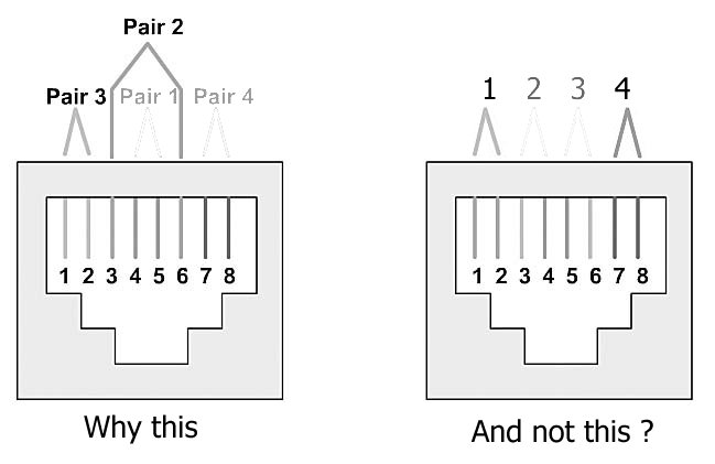
An Ethernet connector seems to use a surprising choice of signal placement in its RJ45 connector. Does anyone know the reasoning behind:
- The decision to make pair 2 straddle pair 1?
- Why Ethernet uses Pairs 2&3 as in the left hand image?
- Why Ethernet does not use E.G. Pairs 1&4 as in the right hand image?
The choice seems odd at the point it comes to lay out the PCB. If we are to make nice differential pair traces, the choice of signal placement is surprising.

