5
\$\begingroup\$

I'm looking at using the following part, S4PM: Datasheet

The part has a Vrrm of 1000V. The mounting pad layout shows a separation of 0.81mm between cathode and anode.

This is well below IPC2221B clearance for 1000V (should be 2.325mm, for a coated board). How can this part be rated for this voltage?

\$\endgroup\$
4
  • 4
    \$\begingroup\$ Interesting question. \$\endgroup\$
    – Andy aka
    Commented May 10, 2017 at 9:19
  • \$\begingroup\$ Maybe you need a creepage slot under there \$\endgroup\$
    – Trevor_G
    Commented May 10, 2017 at 9:24
  • \$\begingroup\$ Maybe it'd be wise to mistrust the component max rating if the assembly isn't potted. \$\endgroup\$
    – Whit3rd
    Commented May 11, 2017 at 0:44
  • \$\begingroup\$ Even if the capsule is CTI 600, it won't help. The creepage for sustained operation is too short. Also, any gap in the PCB you make will be too narrow to count, so you are screwed anyway. Can you immerse it in oil? \$\endgroup\$
    – winny
    Commented May 25, 2017 at 11:14

1 Answer 1

3
\$\begingroup\$

It can be rated for that voltage because it is not a coated FR4 circuit board. As you've said yourself as part of your question, the 2.325mm clearance as stated by the IPC2221B standard is for a 'coated board'.

The epoxy encapsulation needs no such clearance, it will withstand 1000V with that much distance just fine.

Now, you're probably thinking, "but it will be soldered to a circuit board."

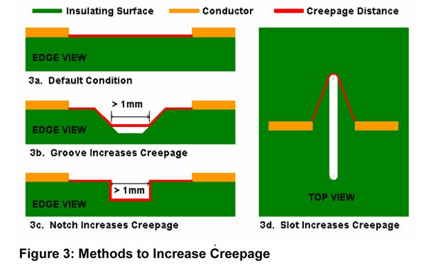
Yes, it will. Make sure you cut an isolation slot underneath it. The 2.325mm clearance is for a continuous PCB, not for a PCB with a slot cut in it providing an air gap. Air can withstand around 3kV per mm, so even a tiny slot will withstand much higher voltages than that same width but occupied with FR4.

You can also cut a groove, this image (which I've blatantly stolen from Andy Aka's answer to this question), should give a better idea of how you can effectively meet the IPC clearance while still having two pads closer to each other than that clearance. diagram of creepage enhancement strategies
Also, make sure you use rounded pads. Arc over is dependent on electric field strength, and sharp corners will concentrate it whereas smooth rounded edges will spread it out.

\$\endgroup\$
1
  • \$\begingroup\$ "The epoxy encapsulation needs no such clearance, it will withstand 1000V with that much distance just fine." No such thing. It can only have CTI 600 as the highest and most plastic capsules are CTI 400. PCB cutout or not, it will creep on the surface of the capsule between anode and cathode. Clearence is easy. Creepage is a nightmare. \$\endgroup\$
    – winny
    Commented May 25, 2017 at 11:16

Your Answer

By clicking “Post Your Answer”, you agree to our terms of service and acknowledge you have read our privacy policy.

Not the answer you're looking for? Browse other questions tagged or ask your own question.