0
\$\begingroup\$

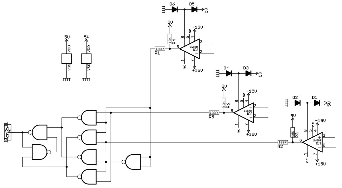
I'm trying to substitute the obsolete NAND chip in this circuit (part of an audio synthesizer) with a standard CMOS one (for example CD4011). The original NAND chip is a DTL chip by Motorola, MC846.

datasheet: http://pdf1.alldatasheet.com/datasheet-pdf/view/130532/MOTOROLA/MC846.html

The pinout is different but I don't care about that, I'm only worried about electrical differences.

I don't think I can just put the CD4011 in place of the MC846, I'm not sure about that but I may need pull-up resistors, and then I read on the MC846 datasheet that it contains "wired OR" and I don't know what that means.

Also, what I'd like is to remove the 5V supply and only use +/-15V. The LM301 comparators are indeed powered by bipolar 15V, but as you can see their outputs are forced to 5V since the MC846 can only be powered up to 5V (is this the purpose of the 2 diodes on the pin 8?) The final output of the NANDs network is going to a normally closed electronic switch circuit
Can anyone help me figure out how to do those mods? thank you

UPDATE

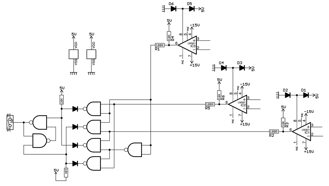
what do you think of these mods? I've added diodes on the output that goes together, and then pullup resistors. Would this work now with CMOS NANDs?

If yes, now I need to understand how to remove the 5V supply (not needed anymore since the CMOS chip can withstand 15V.

enter image description here

\$\endgroup\$

1 Answer 1

2
\$\begingroup\$

The two gates on the left form a simple S-R latch. The other five gates function as a multiplexer that cross-connects the set and reset signals to the latch in either configuration.

Rather than following the topology of the original circuit exactly, you could reimplement the functionality directly in CMOS using a FF and a mux. This would avoid the need to deal with the wired-OR connections..

\$\endgroup\$
3
  • \$\begingroup\$ thanks, I will explore this option (I can see how to replace the S-R latch, but still I can't figure out about the multiplexer)..but also I'd like to understand about the wired-OR and why I can't simply put a 4011 in there \$\endgroup\$ Commented May 22, 2017 at 12:33
  • \$\begingroup\$ 4011 outputs can't be connected directly to each other the way that DTL outputs can. It has to do with the internal circuit structures and exactly how they source and sink current. \$\endgroup\$
    – Dave Tweed
    Commented May 22, 2017 at 12:55
  • \$\begingroup\$ ok, so if I understand correctly, in my circuit that happens twice, two pair of NAND are connected, one forms the S and one the R for the latch. Are those connections forming an OR? if so, could I just join each pair putting a diode on each output and a pulldown resistor (or pullup)? \$\endgroup\$ Commented May 22, 2017 at 13:03

Your Answer

By clicking “Post Your Answer”, you agree to our terms of service and acknowledge you have read our privacy policy.

Not the answer you're looking for? Browse other questions tagged or ask your own question.