1
\$\begingroup\$

StackExchange

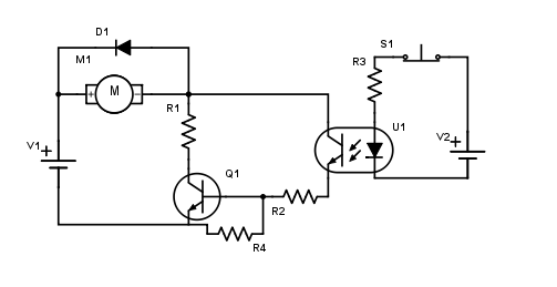
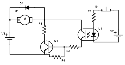
When I was getting help with my last circuit people gave me the advice to add some resistors. So I finally got this result.

Circuit

The stats to the part are the following:

V1: 9V

V2: 5V

M1: RF-130 CH

U1: 4n35 Optoisolator

Q1: BC547 Transistor

I figured out that R3 should be about 70 Ohm due to the forward voltage of the U1 diode being 0.8V and the forward current being 60mA. With R = U/I this brings me to R = (5-0.8) / 0.06 ==> 70 Ohm I just wanted to post this in order to make sure I didn't do any mistake here.

Now comes the harder part as I do not know exactly how to calculate the other resistors. I just wanted to ask if anyone could give me like a general idea where to start calculating all of the missing values.

Thanks for your help.

\$\endgroup\$

3 Answers 3

1
\$\begingroup\$

This circuit doesn't make sense as shown:

Things to fix:

  1. Connect the collector of the opto output to V1+ directly, not to the switched power to the motor. As it is now, the opto turns on Q1, which lowers the voltage on the right side of the motor, which robs power from the opto, which decreases how much Q1 is turned on. That makes no sense, and is probably bad for the motor and Q1.

  2. Lose R1. It gets in the way of the motor drawing current. That greatly reduces the motor torque, and causes unnecessary dissipation and wasted power in R1. Connect the right side of the motor directly to the collector of Q1.

\$\endgroup\$
2
\$\begingroup\$

R1 should be zero ohms, but the collector of the optoisolater should be connected directly to the positive terminal of V1.

In order to make sure it's saturated, the base current for Q1 needs to be somewhat greater than the motor current divided by Q1's worst-case (lowest) current gain, so R2 should be V1 divided by the base current.

The purpose of R4 is to prevent leakage current through the opto from turning on Q1, so its value needs to be less than 0.6V divided by the worst-case (highest) leakage current value.

\$\endgroup\$
0
\$\begingroup\$

Note: In your previous Q you said you're going to drive that with a PWM signal. It is importaint for resistor selection!

Recommended current for the LED of the oprocoupler is 10mA and its fwd voltage drop is 1.3-1.5V. I don't know where did you got those 70ma and 0.8V. So R3 should be about 360 ohm. Your formula is correct, the values are not.

Collector of the optocoupler is better to be connected to battery (+).

R1 can be omitted if your motor's rating is OK for 9V.

R2, R4 can take a variety of values, but setting them both to 4.7k would work fine here. Optocoupler CTR (current transfer ratio is 50-100%, so if you put it 10mA through the LED you can get out of its transistor between 5 and 10mA. A 4.7k resistor will draw about 1.7mA for 9V supply minus 0.7V B-E drop of BC547 minus optocoupler's transistor saturation C-E voltage 0.3V, so it is OK. The other resistor is used to quickly discharge the base and turn off the transistor when optocoupler current stops.

\$\endgroup\$

Your Answer

By clicking “Post Your Answer”, you agree to our terms of service and acknowledge you have read our privacy policy.

Not the answer you're looking for? Browse other questions tagged or ask your own question.