For a project we use a brushless DC (BLDC) motor. Everything works fine until we tried to reach high velocities. I will first explain my setup, and than explain our problems using some graphs. Unfortunately I don't have enough points to put al my images in separate links, so they can be found here.
1.0 Setup
The following hardware is used in the setup:
- BLDC motor: Tiger motor U8 (135kV)
- Motion controller: SOMANET DC 1K
- Encoder: RM08 12 bit absolute encoder
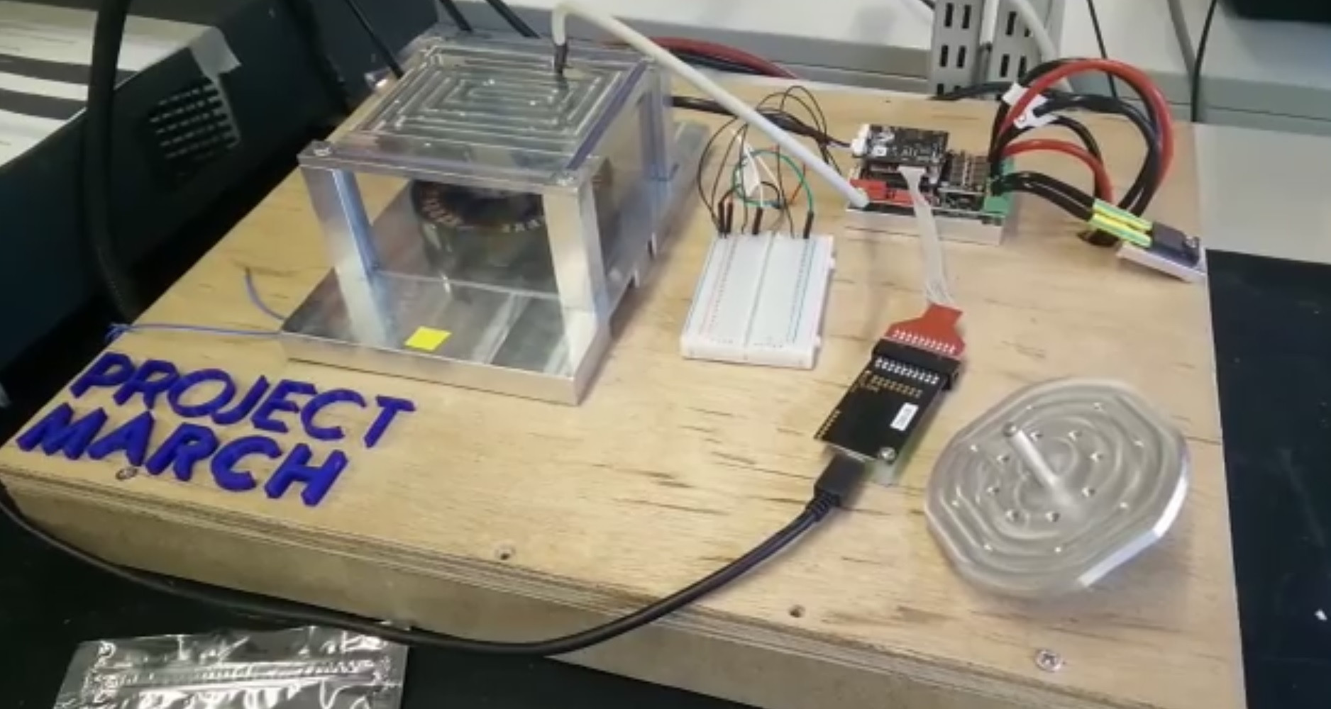
An overview of the setup can be found in image (1)
1.1 Requirements and Parameters
We need about 4800 [RPM] from the motor. The Tiger motor has a kv value of 135 [RPM/V], connecting it to a 48 [V] supply means it theoretically should be able to go up to 6500 [RPM]. The specsheat includes a scenario where it reaches 5000 [RPM] while a propeller is connected to it, so 4800 [RPM] with no load should not be a problem.
2.0 Problem
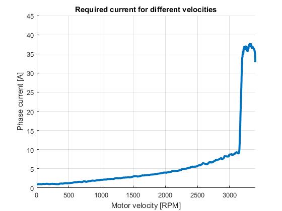
We are not even getting close to the 4800RPM, a plot of the motor velocity vs phase current is shown in image (2). We can identify 2 problems from this plot.
2.1 Inefficient commutation
The first thing which was remarkable from the test is that about 10 [A] was already required to turn at 3200 [RPM] without any load connected. This seems to be caused by inefficient commutation, we figured there are two main possible causes for this.
2.1.1 Phase offset error
Their might be an error in the phase offset used, this will cause an linear increase in required current with velocity. This can be best solved by finetuning the offset at a high velocity. However our curve does not seem linear, thus this does not seem to be the case.
2.1.2 Delay error
There is a certain amount of delay in between requesting the position from the RM08 and applying the new voltage. This delay can cause the current to exponential increase with motor velocity, which is true in our case.
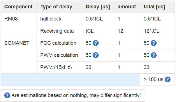
By adding up al delays we found a total delay of ~0.1 ms in the system (see image (3)). Spinning at 3000RPM = 50Hz and using 21 pole pairs means that the electrical turning frequency is 1050Hz, than a delay of 0.1 ms would cause a 37.8 electrical degree error, This likely causes the inefficiency!
2.2 Control going crazy
if we try to go above ~3200 RPM, the motor starts pulling a lot of current and makes a lot of noise. This means the motor is not operational above 3000RPM, this seems to be the most urgent problem at the moment.
Voltage dependency
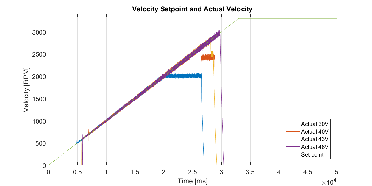
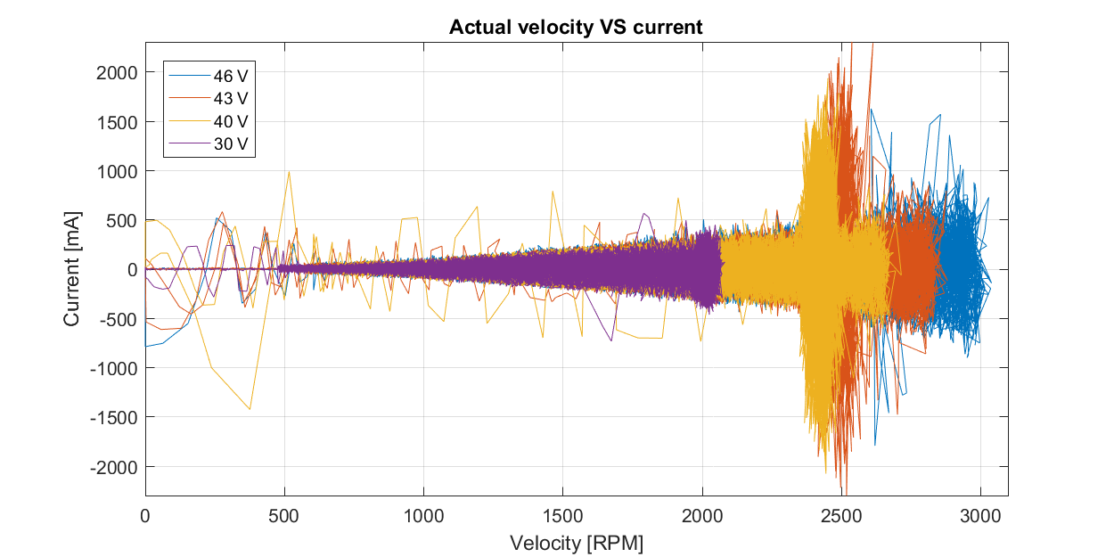
Normally the motor velocity is limited by back-EMF, if the back EMF would be causing this issue the problem would be voltage dependent. Therefore some measurements where done at different voltage levels, see image (4) and 卌.
The moment where the motor stops following the velocity sweep seems to increase linearly with voltage. Another interesting outcome is that at 30V the motor just stops following the velocity sweep, while at the higher voltages (40V and 43V) the motor suddenly dropped to a lower velocity. Note that the 46V test stopped before this moment because to high current peaks were flowing trough the SOMANET (35A). However it seems unlikely the back-EMF is the problem since Tiger has been able to reach 5000RPM themselves.
Solutions
For the first problem we thought we could use something like:
Pcorr = Penc + t_delay * Vel.
With:
- Vel: angular velocity
- t_delay: the delay compensation gain
- Penc: the encoder position for the rotor
- Pcor: the delay compensated position
However this didn't save the problem at all. Do you have any other suggestions?
For the second problem we can't think of any cause, can you think of any?

