2
\$\begingroup\$

I'm trying to make a homebrew CPU but having problems with the 74LS181 ALU, which I'm simulating in Logisim software before diving into real ICs and breadboards.

I've cascaded two 74181 following instructions found in many sites such as this.

This works fine with most of addings I tried, but some don't work.

For example:

0010 0111 (39 in decimal) + 0000 0001 (1)

leads to a 0010 0000 (32) result.

I know it should have something to do with the fact that 74181 uses signed numbers represented in two's complement. The least significant nibble in the example (0111) represents the max positive number with 4 bits, so when incremented by one goes to zero...

Is there any way to make 74181 work with only positive numbers? Or solve this issue in any other way.

I'm frustrated because with this problem the ALU is completelly usesless.

link for 74181 datasheet

link for project (has image of error on simulated ALU) - link on comment bellow

\$\endgroup\$
5
  • \$\begingroup\$ 1. Show a schematic 2. That book link isn't working, at least for me. 3. Link to data sheet so people don't have to look it up. \$\endgroup\$ Commented Jun 21, 2017 at 21:26
  • \$\begingroup\$ 1. Hosting image sites are blocked at job :(. Posted image at project page (it's the fourth image in gallery): hackaday.io/project/24511-jaca-1-2-homebrew-cpu \$\endgroup\$ Commented Jun 21, 2017 at 21:37
  • \$\begingroup\$ 2. The book link is working for me \$\endgroup\$ Commented Jun 21, 2017 at 21:37
  • \$\begingroup\$ 3. Edited the question and added a link to 74181 datasheet pdf. Sorry \$\endgroup\$ Commented Jun 21, 2017 at 21:39
  • \$\begingroup\$ Just occured me that this can be a problem on this specific implementation of 74181 for Logisim (I downloaded circuit library add-on from this guy: 74x.weebly.com/blog/library-of-7400-logic-for-logisim). It's not official part of the Logisim. \$\endgroup\$ Commented Jun 21, 2017 at 21:44

4 Answers 4

2
\$\begingroup\$

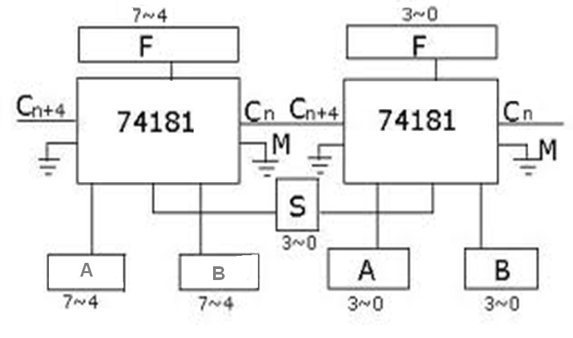
Please show how you are interconnecting the two devices, particularly the carry from the LSB to the MSB device. It looks like that may not be wired correctly.

The 74LS181 doesn't deal with signed numbers, just unsigned integers. It is up to you to interpret the values in the form you need.

The two devices should be interconnected similar to this:

74181 8-bit ALU

\$\endgroup\$
1
\$\begingroup\$

Based on your example of the error, you don't have Cn and Cn+4 connected correctly. Your Cn input is floating and inputting a phantom carry-in and adding an unintended +1 to the low stage. And the upper stage which should receive a carry-in looks like it is tied low instead.

Your problem is not related to signed vs. unsigned binary numbers. The adder works the same on each bit stage regardless of your interpretation of what the binary represents. That's the beauty of 2's complements. The logic circuits for each bit stage is the same (generally). You just interpret the values differently.

\$\endgroup\$
1
  • 1
    \$\begingroup\$ You are right about the two points. I misconnected the Carry input and output (actually inverted them between Hi and Lo nibbles). And the two's complement binary operations are exactly the same as unsigned binary, it's just the way to interpret the numbers that changes (now I know, at the moment of the question i didn't know). Thank you for the help \$\endgroup\$ Commented Jun 22, 2017 at 13:02
1
\$\begingroup\$

All the answers helped me in finding the bug. Actually the error was in the implementation of 74181 ALU in Logisim, as I supposed. There are 3 file versions of the chip, but the right one is (strangelly) the v2 not the v3. I will put a comment on the author's page to warn others in the future.

Besides this the Carry output/input connection was inverted, should be from the ALU of Low nibble (4 least significant bits) to the High nibble. I made the opposite. My mistake.

Thanks everyone.

\$\endgroup\$
0
\$\begingroup\$

First, get rid of the 2nd 181. Concentrate on getting a 4-bit result and understanding it.

Second, combining 0111 and 0001 to get 0000 is very strange, but for instance, if you are applying 0001 to the A inputs, and 0111 to the B, and a Mode select of 1111, you'll get A - 1, or 0000. So I'd recheck your select lines and your inputs. I'd especially check things like a swap between pins 2 and 3, which would confuse A0 and S0.

\$\endgroup\$

Your Answer

By clicking “Post Your Answer”, you agree to our terms of service and acknowledge you have read our privacy policy.

Not the answer you're looking for? Browse other questions tagged or ask your own question.