2
\$\begingroup\$

Below is what Matt L.said in the thread here. Could anyone clarify how Fourier transform be able to deal with transitents? Reading that thread many times but I couldn't figure it out.

Note that it is not true that the Fourier transform cannot deal with transients. This is just a misunderstanding which probably comes from the fact that we often use the Fourier transform to analyze the steady-state behavior of systems by applying sinusoidal input signals that are defined for −∞ < t < ∞.

\$\endgroup\$
3
  • \$\begingroup\$ Does this help? link.springer.com/chapter/10.1007%2F0-387-28799-X_4 \$\endgroup\$
    – Janka
    Commented Jul 13, 2017 at 22:53
  • \$\begingroup\$ For any signal of any duration, we sample the (time-limited) signal, then apply a windowing function. (turning on and off the sampler is a rectangular window). This is the start of spectral analysis. check : en.wikipedia.org/wiki/Window_function#Spectral_analysis it is a very interesting field of maths with lots of applications too. \$\endgroup\$
    – user55924
    Commented Jul 13, 2017 at 23:50
  • \$\begingroup\$ With transients, the lower limit of integration often gives rise to problems since the Fourier integral goes to infinity (if, e.g., the transient tends to infinity for negative time) . One solution is to assume unilateral signals, so f(t)=0, t<0, i.e. multiply time functions by the Heaviside function: f(t)H(t) \$\endgroup\$
    – Chu
    Commented Jul 14, 2017 at 8:28

5 Answers 5

4
\$\begingroup\$

Check out any reference on Gibbs phenomenon. It essentially says that the Fourier series cannot fully accurately represent any repetitive signal with discontinuities. What one gets when the series is added is a wave form that converges to the original except at the points of discontinuity. AT those points, one gets an oscillatory behaviour with overshoot as higher and higher frequencies of the series are accumulated to "rebuild" the original signal. Waveforms with extremely fast transients come arbitrarily close to having discontinuities at the points where there is a signal level transition, so a very small error is expected in the use of the transform. In any case, nature inhibits these transitions from being infinitely fast. Also bandwidth restrictions will probably be a larger source of error.

\$\endgroup\$
3
\$\begingroup\$

It's important to use the right sort of tool for the job. A hammer is defined to put in nails. If you want to turn screws, use a screwdriver.

The Discrete Fourier Transform (DFT), of which the Fast Fourier Transform (FFT) calculates exactly the same result, but far faster, is defined only over repetitive signals. That is, the result it produces is exactly the same (with appropriate re-labelling) as if you had taken the signal input to the FFT, and concatenated it with itself.

This cyclic feature means that the FFT is a natural fit for repetitive waveforms. If the input sample contains an exact integer number of cycles, then it can be extended indefinitely by repetition, and look exactly the same as the original.

The technique of windowing a signal before FFT is used to reduce the problems that occur when it's used to transform a non-cyclic waveform. For example, take a one-second sample of a continuous 10.5Hz signal. If this sample is concatenated with itself, you get a half-cycle step, which messes with what you would hope to see doing a spectrum analysis. Note that it doesn't make the transform wrong, it just means that what you got is not what you naively hoped to get. If you hit the nail sideways, you get a bent rather than a driven nail, the hammer is still working just fine, doing exactly what it's defined to do.

The window reduces the signal amplitude at the beginning and end of the sample to zero, which means it can be cyclically extended. The window changes the signal, so the spectrum will change. However, it changes in a known and easily calculable way, which the FFT doesn't further change.

When used to transform a transient signal, we need to ensure that the signal sample starts and ends at zero. Then the sample meets the cyclic requirement, and the FFT will give you exactly what you would expect if you had a train of transient signals, repeating every sample length.

That's what the FFT does. If you don't want the transform of a train of signals, then the FFT is not the hammer to use. You still have a lot of freedom to adjust this train of signals to your taste, just as you can choose what window to use when transforming a continuous signal. You can make the impulses repeat less often by increasing the time length of the sample for instance.

\$\endgroup\$
2
\$\begingroup\$

I'm not trying to get to the bottom of the linked question, I'm just trying to justify why Fourier analysis of a transient is perfectly feasible.

Given that a transient is temporal limited, i.e. it is a transient and it doesn't last very long, it's feasible to limit the time range for the analysis. On this basis, it seems reasonable to analyse it if it were a continual and repeating waveform. So the transient begins at (say) time zero and is all-done at (say) 1 second. Is there anything unreasonable to assume that it starts again at t=1 second?

Therefore it can be analysed by normal Fourier analysis.

\$\endgroup\$
7
  • 1
    \$\begingroup\$ But what you are analyzing is continual and repating waveform not just a short time transient one. Is the result still same? \$\endgroup\$
    – emnha
    Commented Jul 16, 2017 at 6:00
  • \$\begingroup\$ If the transient builds up and dies away within the time window you choose (and this is important) then you get the same result. If there are significant continuous signals in the background then these cannot be ignored so, if you extend the time window to accommodate full cycles of the background (but numerically significant) continuous signals then you have extended the time transient window (not a problem because it had died away) AND synchronized the window with the continuous signal. \$\endgroup\$
    – Andy aka
    Commented Jul 16, 2017 at 8:49
  • \$\begingroup\$ The time window you have then chosen defines the inverse of the lowest frequency used in the fourier analysis. So if you chose 3.7 seconds (and you do need to do this so that the above criteria are met), then the lowest frequency sine and cosine are at 0.27027 Hz with harmonics ranging from that point. \$\endgroup\$
    – Andy aka
    Commented Jul 16, 2017 at 8:52
  • 1
    \$\begingroup\$ I think the definition "transient" here is different from what I really meant to say. With transient, I would like to know if we can use Fourier transform to solve for circuit problems with initial conditions like what we usually did with Laplace transform. \$\endgroup\$
    – emnha
    Commented Jul 19, 2017 at 20:41
  • 1
    \$\begingroup\$ It is something like inductor current or capacitor voltage at time t = 0 in RLC circuits. \$\endgroup\$
    – emnha
    Commented Jul 19, 2017 at 22:10
0
\$\begingroup\$

Waves are subject to quantum uncertainty principles. Higher accuracy in the frequency domain leads to lower accuracy in the time domain. Fast signals with a transient timing can appear to have lower volume or a wider frequency band than would be accurate.

Is difficult to know exactly the sample when a signal starts an ends based on the fft because those are transient moments of the signal.

The most accurate time frequency algorithm is the vigner time frequency distribution, which is slower and high resolution and my preferred method is filter banks, arrays of a thousand bounce pass filters...

There is also a DSP forum on the website with people that specialize in fft.

\$\endgroup\$
-1
\$\begingroup\$

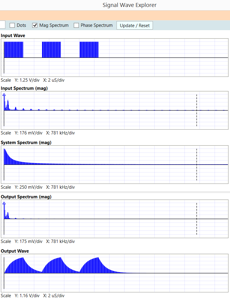
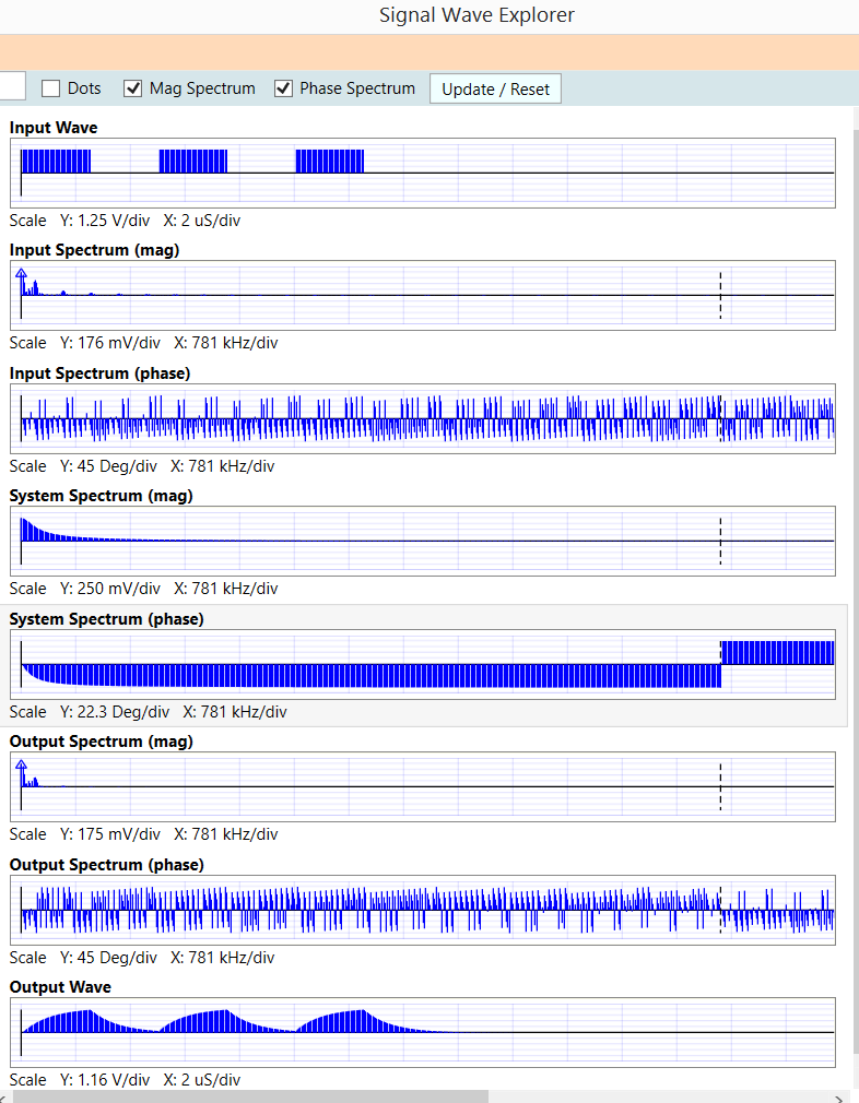
Here is Signal Wave Explorer, using FFT, to model 3 pulses thru a LPF. On right side of the plots is a dotted vertical line, the Nyquist frequency. In the Mag/Phase that is the mirroring frequency, indeed shown here.

[ We are interested in very accurate modeling of the SETTLING of opamp responses, to the 16 and 20 and 24 bit levels. Thus far, in SWE, with 512,000 samples, we easily reach the 20 bit level. With larger memory allocation, we expect to reach 24+ bits. The built-in example "JB stage", shown at end of this answer, illustrates typical problems of settling. ]

Shown below these 8 plots is screenshot with just InputWaveform, Magnitude plots, and OutputWaveform. Examine the OutputWaveform carefully, particularly the 3rd output pulse, and you'll see that final decay to zero amplitude. The first 2 pulses are not allowed enough time to decay to zero amplitude.

Thus we have used the FFT to fully capture the transient behavior.

enter image description here

And now without the Phase plots. In the InputSpectrum, you see the sin(x)/x components of the squarewave, with amplitudes decaying as 1/Harmonic#. The tool --SWE--- simply multiplies this InputSpectrum with the SystemSpectrum, producing the OutputSpectrum; magnitudes are multiplied; phases are added. Then OutputSpectrum undergoes InverseFFT, to produce the OutputWave.

enter image description here

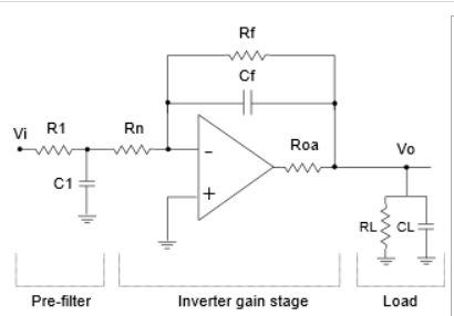
Here is the JB_stage example.

enter image description here

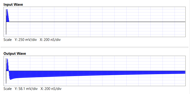
Here is output waveform of JB_stage, with NO input filtering (C1 is not active); notice the initial pulse is NONINVERTING. The input edge blasts right through the feedback capacitor.

enter image description here

\$\endgroup\$
2
  • \$\begingroup\$ Can you elaborate what are you trying to explain here? \$\endgroup\$
    – Mayank
    Commented Jul 14, 2017 at 5:09
  • \$\begingroup\$ I don't understand. \$\endgroup\$
    – Unknown123
    Commented Apr 5, 2022 at 10:04

Your Answer

By clicking “Post Your Answer”, you agree to our terms of service and acknowledge you have read our privacy policy.

Not the answer you're looking for? Browse other questions tagged or ask your own question.