2
\$\begingroup\$

I am doing a personal project to learn a bit about electronics but I do not have much prior knowledge about it.

I am using a STM32L476RG microcontroller, a 3 digit seven segment display (common cathode), a 1N4148 diode and a 220Ω resistor.

My initial issue was that when the digit was meant to be off (but the segments should be on to light other digits), there was a dull light on the segments. To get around this, I put a 220Ω resistor in series with the common pins on the seven segment display. This fixed the issue of the digit being dull when it should be off, but it made the digits dull when they were meant to be on.

So to bypass the resistor when the digit is meant to be on, but not when the digit is meant to be off, I added a small signal diode in parallel with the resistor. A diagram of a single segment in this layout looks like the below. This shows the diode and resistor attached to pin 12 (the pin that controls digit 1 being on or off).
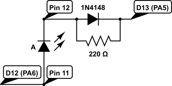
schematic

simulate this circuit – Schematic created using CircuitLab

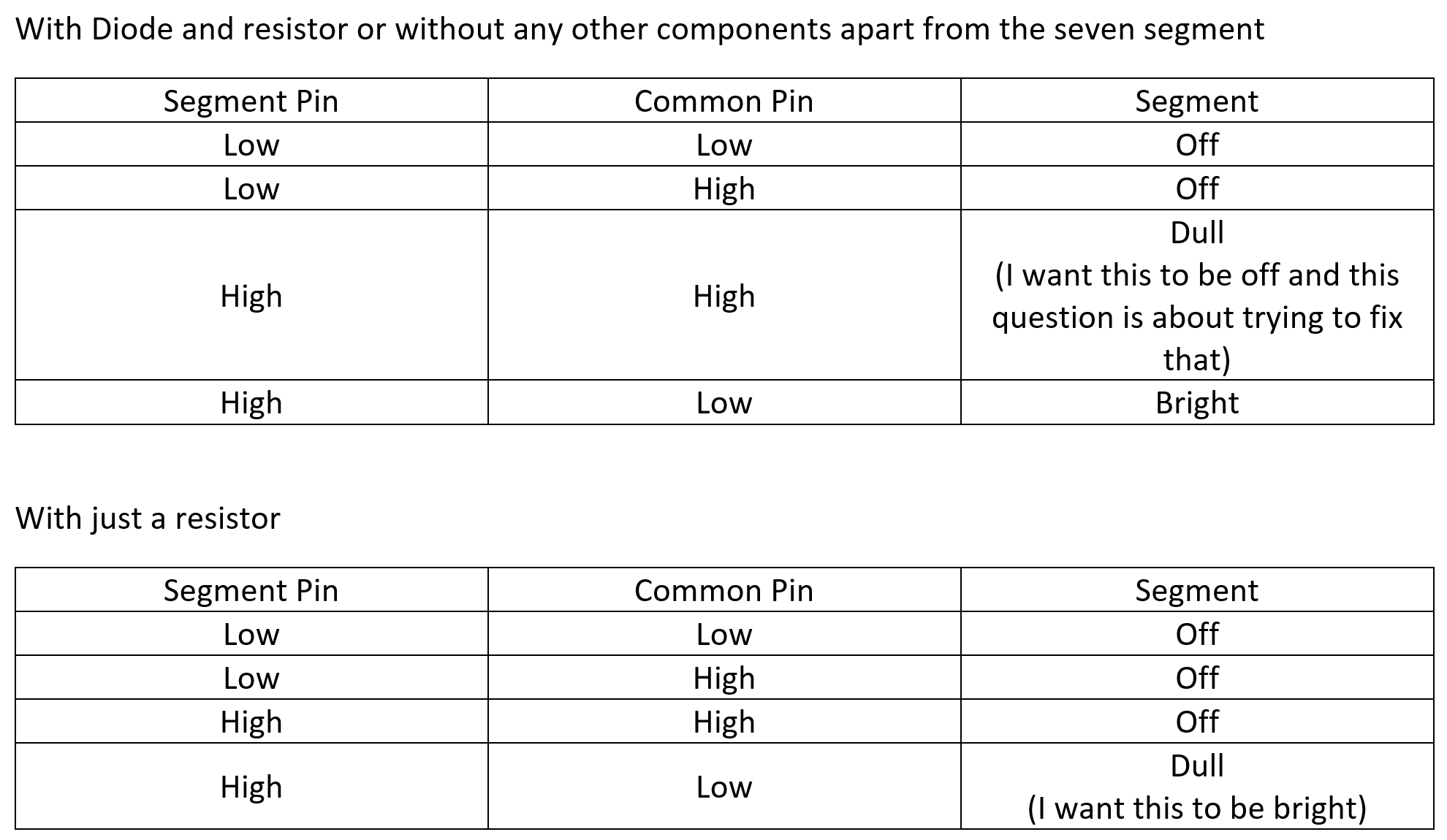
The way I thought this would work was when the segment pin is high and the digit pin is low, the segment would be on and be bright (which it is) as it goes through the diode. But when the segment pin is high and the digit pin is also high, the segment would be off as it is going through the resistor. However, this is not the case, when both pins are high, the segment is on and dull as if it were still going through the diode.

What am I doing wrong?


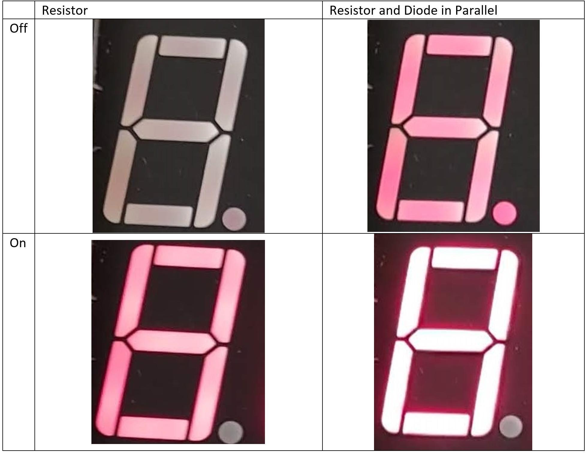
A comparison of the when the diode should be on and off with the resistor and the resistor / diode. The segment pins are all high and it is the common digit pin that is high for off and low for on.

Level of light comparison.


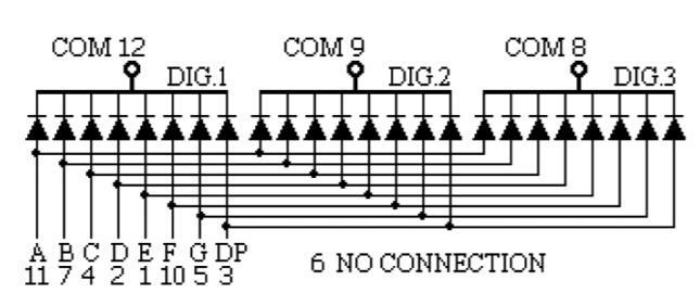
The 3 digit 7 segment display pin layout for reference.

The pin layout of the seven segment display.


Edit

enter image description here

\$\endgroup\$
24
  • \$\begingroup\$ Why are both sides connected to a port pin on the micro? You don't seem to have a ground connection anywhere? \$\endgroup\$
    – MCG
    Commented Mar 19, 2020 at 15:47
  • \$\begingroup\$ @MCG Both sides are connected to the microcontroller as the segment pins are shared across the three digits and so to show different numbers, you have to quickly turn on and off each digit using the pins 8, 9, 12 (I think). If pin 12 was connected to ground, would that not force the digit to always be on? Or do I also need to attach it to ground somehow? I edited the question to show the pin layout of the 7 segment display. I appreciate any help you can offer :) \$\endgroup\$
    – Dan
    Commented Mar 19, 2020 at 16:07
  • 1
    \$\begingroup\$ What's your logic level? 220Ohm is too high for 3.3V \$\endgroup\$
    – Sim Son
    Commented Mar 19, 2020 at 18:19
  • 2
    \$\begingroup\$ Your question is the classic "XY" problem. You have a problem, and ask how to implement your solution rather than asking how to solve the problem. The correct question here is: "Why are my LEDs on when I thought I told them to turn off?" \$\endgroup\$
    – JRE
    Commented Mar 19, 2020 at 20:10
  • 1
    \$\begingroup\$ Actually, a better question would have been: "How do I drive my LEDs with this processor?" \$\endgroup\$
    – JRE
    Commented Mar 19, 2020 at 20:25

2 Answers 2

5
\$\begingroup\$

It shouldn't be necessary to play funny games with resistors and diodes. Lighting LEDs with a microprocessor output is a normal thing to do, and shouldn't require any kind of overly clever circuitry.

  1. Make sure you are setting the common to high, and not simply "high impedance." You want it driven to a high state, not simply floating. You want to use "push-pull" outputs, not "open-drain."
  2. Make sure you aren't switching on a pull down on the common. All GPIO pins can have independently set pull up or pull down resistors. These are internal to the chip and can be turned on and off through software.

From the datasheet:

Each of the GPIO pins can be configured by software as output (push-pull or open-drain), as input (with or without pull-up or pull-down) or as peripheral alternate function. Most of the GPIO pins are shared with digital or analog alternate functions. Fast I/O toggling can be achieved thanks to their mapping on the AHB2 bus. The I/Os alternate function configuration can be locked if needed following a specific sequence in order to avoid spurious writing to the I/Os registers.

From the GPIO application notes:

STM32•GPIO exhibits the following features:

Output states: push-pull, or open drain + pull-up / pull-down according to GPIOx_MODER, GPIOx_OTYPER, and GPIOx_PUPDR registers settings

It is entirely possible that you have your output set to open-drain with a pull down. That would let current flow through the common pin even when it is supposedly set to "high."

Another problem you have is that the common is only allowed to sink 20mA. If you have 8 GPIOs driving 8 LEDs at 3mA, then you've exceeded the maximum allowed current of the GPIO pin you are using as common.

Even if you fix the problem of "ghost lighting," you are still in danger of killing your processor.

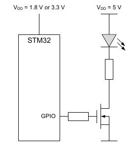
The GPIO application notes give the following example for driving high currents from your processor:

enter image description here

It doesn't matter that the example shows the LED powered from 5V. It's the same concept regardless of the supply voltage. It'll work the same with 3.3V.

Conclusion:

  1. Use an external transistor to drive the common.
  2. Use current limiting for the LED segments.

To limit the LED current through the LEDs:

You processor is allowed a maximum of 8mA per pin when sourcing current, up to a total of 150mA.

8 LEDs at 20mA would exceed that maximum rating.

Your LEDs have a forward voltage of about 1.7V, and you are using them with a 3.3V powered microprocessor. You need to limit the current to less than 18mA per LED. Given a voltage drop of 1.6V, that's a resistor of at least 90 ohms. Your 130 ohms was probably a good start, but 220 is probably better.

You must use a resistor for each LED segment, not one per common.

\$\endgroup\$
2
  • \$\begingroup\$ This is a great answer, thanks. I'll build that up over the next few days and accept it. I'm afraid I don't know much about transistors either. Will any work for this? For example, if i buy this one, will it work? \$\endgroup\$
    – Dan
    Commented Mar 20, 2020 at 6:19
  • \$\begingroup\$ My transistors finally came and I was able to wire this up yesterday. It works great. Thanks for your help \$\endgroup\$
    – Dan
    Commented Mar 27, 2020 at 10:13
2
\$\begingroup\$

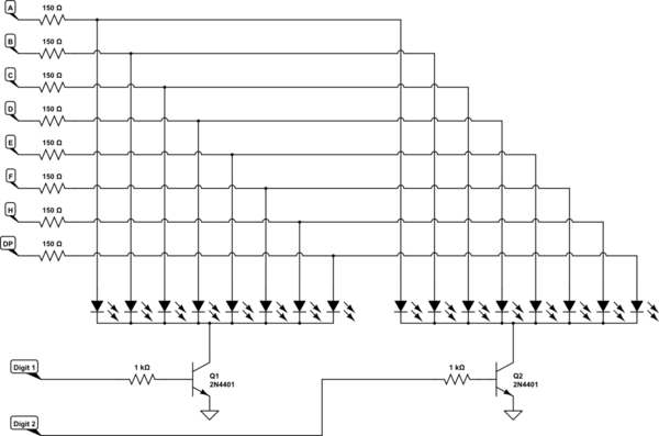
Here is what the display circuit should look like (showing 2 of 3 digits to make the schematic readable):-

schematic

simulate this circuit – Schematic created using CircuitLab

Each segment has a resistor to set the LED current, common to all digits. Each digit has a transistor to pull the common Cathodes of that digit down, with a resistor setting the Base current. With sufficient Base current the transistor can easily sink the current of all 8 LEDs in its digit.

Both the segment and digit outputs from the MCU are active high. In operation a digit is displayed by first turning off all digits, then applying the segment code for one digit, and finally turning on the digit for a period. This is done for each digit in turn, fast enough to avoid visible flicker. During the time that each digit is being displayed the MCU can do other jobs such as reading switches etc.

If you get 'ghosting' then increase the 'blanking' time between turning off one digit and turning on the next. You can also increase the blanking time to reduce LED brightness.

\$\endgroup\$
2
  • \$\begingroup\$ Thanks for the answer. This is helpful to see :) \$\endgroup\$
    – Dan
    Commented Mar 21, 2020 at 7:41
  • \$\begingroup\$ My transistors finally came and I was able to wire this up yesterday. It works great. Thanks for your help \$\endgroup\$
    – Dan
    Commented Mar 27, 2020 at 10:14

Your Answer

By clicking “Post Your Answer”, you agree to our terms of service and acknowledge you have read our privacy policy.

Not the answer you're looking for? Browse other questions tagged or ask your own question.