0
\$\begingroup\$

I am interested in finding Vgs for E-MOSFET for desired Id or/and Vds. Referring to those equations of drain current in saturation region, value of conduction parameter "K" would be nice to have but it isn't given by any data sheet. For me it seems, that calculating Vgs through Id is impossible, if this mentioned parameter is not given.

I have been trying to find any other useful formula, but without success.

  • So I am wondering, if anyone else maybe knows formula for determining Vgs for given Id or/and Vds?

The formula I was referring to: enter image description here

\$\endgroup\$
3
  • 1
    \$\begingroup\$ This is the main reason why almost no one builds single stage A amplifier. \$\endgroup\$
    – G36
    Commented Aug 2, 2017 at 19:45
  • \$\begingroup\$ @G36 In which class of amplifier is mosfet more often used then? \$\endgroup\$
    – lucenzo97
    Commented Aug 3, 2017 at 7:22
  • \$\begingroup\$ In power amplifiers as an output stage (source follower). In this case, we do not care about the K factor. \$\endgroup\$
    – G36
    Commented Aug 3, 2017 at 11:24

2 Answers 2

4
\$\begingroup\$

If you want to apply that formula to any real, discrete, device, then it is not going to work, even if the datasheet mentioned K.

The fact is, that real discrete device sport a wild variation of parameters, in particular Vth. Therefore, even if you knew a fairly precise value of K, it wouldn't matter much, because in the inverse formula you would have Vth as a parameter.

Consequently, any value of Vgs you would get would be highly inaccurate, unless you measured the Vth of the specific device.

Of course if you can measure quantities on a real specimen, you would be able also to measure Vgs, so the whole point in deriving that formula might be moot. In fact, with some patience and a relatively simple circuit, you could characterize the device yourself, by measuring Id vs Vds at different Vgs levels, and plotting the output curves of the device.

To be more specific, here is an excerpt from a datasheet of a jellybean enhancement MOSFET (2N7000G; emphasis mine):
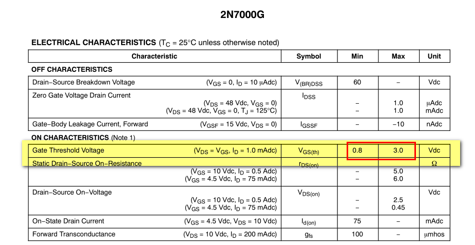
enter image description here

As you can see, Vth is specified with very loose tolerance, therefore you could expect the same tolerance on the values of Vgs obtained by inverting that formula.

\$\endgroup\$
3
  • \$\begingroup\$ So, in case of audio amplifier, I would need to only bias the transistor so the Vgs is somewhere between 0.8V and 3V (in your case of your transistor)? \$\endgroup\$
    – lucenzo97
    Commented Aug 2, 2017 at 18:29
  • \$\begingroup\$ @Keno No! Probably you haven't understood the meaning of those min/max values. The datasheets is telling you that every specimen of that MOSFET (statistically speaking) has a Vth guaranteed to lie between those limits. You may have a bag of those and one could have, say, a Vth=1V and another a Vth=2.5V randomly. \$\endgroup\$ Commented Aug 2, 2017 at 18:41
  • \$\begingroup\$ @Keno A good design is a design that takes into account the worst case. For an audio amplifier, if you mean a class A amplifier (one MOSFET biased in its saturation region), the design is tricky, because you cannot know in advance where Vth lies precisely. Probably you will need some kind of trimpot to manually adjust the bias on the field. \$\endgroup\$ Commented Aug 2, 2017 at 18:44
1
\$\begingroup\$

Haven't we talked about it yet? If you want to know the exact value for \$K\$ factor for a given MOSFET you are forced to measure it in your benchtop (\$K = \frac{I_D}{(V_{GS} - V_P)^2}\$)

Or you can try to guess the \$K\$ factor from the datasheet.

From the datasheet

http://www.onsemi.com/pub_link/Collateral/2N7000-D.PDF

To find \$K\$ factor we need \$Vgs(th)\$

So I pick average \$Vgs(th)\$ value

\$V_{max} = 3V\$ and \$V_{min} = 0.8V\$

$$Vgs(th)= \frac{3V + 0.8V}{2}= 1.9V$$

I also need \$Id\$ current for a given \$Vgs\$ voltage

So I use figure 1 or figure 2 and read the \$Id\$ for a given \$Vgs\$

I pick randomly \$Vgs = 5V\$ And I use figure 1 to find \$Id\$ current for \$Vgs = 5V\$

In reality, we don't calculate K factor. Because of the fact that the MOSFET show great process spreader.

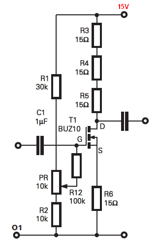
We simply use a voltage divider plus a potentiometer to select the right bias point.

See the example diagram:

enter image description here

The voltage gain is set by

$$Av \approx \frac{R_3 + R_4 + R_5}{R_6}\approx 3V/V$$

And next, you are using pot PR to set drain voltage equal to \$7.5V\$ (0.5Vcc)

\$\endgroup\$

Your Answer

By clicking “Post Your Answer”, you agree to our terms of service and acknowledge you have read our privacy policy.

Not the answer you're looking for? Browse other questions tagged or ask your own question.