DISCLAIMER : this question is somehow related to this other question of mine, but the latter did not have any satisfying answer.
I'm working on an audio DSP project with the STM32F4xx, using 4 audio inputs and 1 audio output.
I need to - read each input - process each input's signal, - mix the processed signals together - output the result.
The input is obtained via one of the 3 STM32's internal DACs, 1 channel for each input (ie 4 channels to scan in total) and stored to a buffer using DMA.
The output is converted through a codec using an I2S bus, at 48kHz.
Everytime the codec has finished converting a buffer (or more precisely a half-buffer), it triggers a callback function in which I currently have all the DSP code. In the loop, the output samples are computed and sent to the half-buffer to be output using DMA to I2S.
Granted that I sample my input at the same rate as my output (48kHz which means that my DAC must be clocked at 4*48kHz=192kHz), how can I synchronize the ADC and the DAC conversion?
I have thought of a FIFO inbetween the input and the DSP routine, picking a sample in the queue everytime I need to process one. But I am not sure how to do that when working with chunks of data (a buffer has a depth of 64 samples).
Another solution would be to have an input buffer depth of only 1 sample, and to read this sample in the DSP routine but I am not sure weather this would work.
Does anyone knows what is the best way to do that? Or even better, how to synchronize the STM32's ADC to an external codec?
EDIT: I also thought of using the DAC in "one shot" mode ie triggering a conversion of 64 samples for all the channels everytime my codec raises its "I want samples" flag. Would that work?
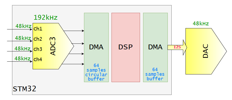
EDIT2: Upon request of @Neil_UK, here is an illustrative diagram of what's happening :

4 inputs are being sampled by the internal ADC of the STM32. Each must have a sampling rate of 48kHz so, given that the conversion of ADC channels is not done in parallel, that gives us a total scanning frequency of 192kHz (correct me if I'm wrong).
Then, each input's converted samples are stored in a circular buffer of 64 samples each and an interrupt flag is raised every time a half buffer has been filled (ie 32*4 samples have been stored).
On the other side there is a codec which continuously converts samples that are being sent to it via I2S, from the STM32's DMA. There is also an interrupt triggered every time the half I2S buffer has been emptied. Between the 2 there is a DSP routine that is supposed to read the input, filter it and put it in the output buffer.
The problem: I have 2 interrupts:
- The "I'm done converting" raised by the codec (DAC) ;
- The "I'm done converting" raised by the internal ADC.
If I scan at 192kHz, these interrupts should at least be in sync (except for some jitter maybe) but the phase can be completely different. That means that I can have my DAC noticing me that all the samples are sent while my ADC is still in the middle of converting the inputs. And this phase difference can potentially be different every time I reset the board, so I can't really compensate it with an offset.
EDIT3 : It seems like the SAI module is a good way to do that, if anyone has experience with SAI I'd love to have some tips and help on how to use it to interface the internal DAC with an external codec

end_of_conversionflags not being raised at the same moment. EDIT : actually I have to go, I'll edit my post asap \$\endgroup\$