0
\$\begingroup\$

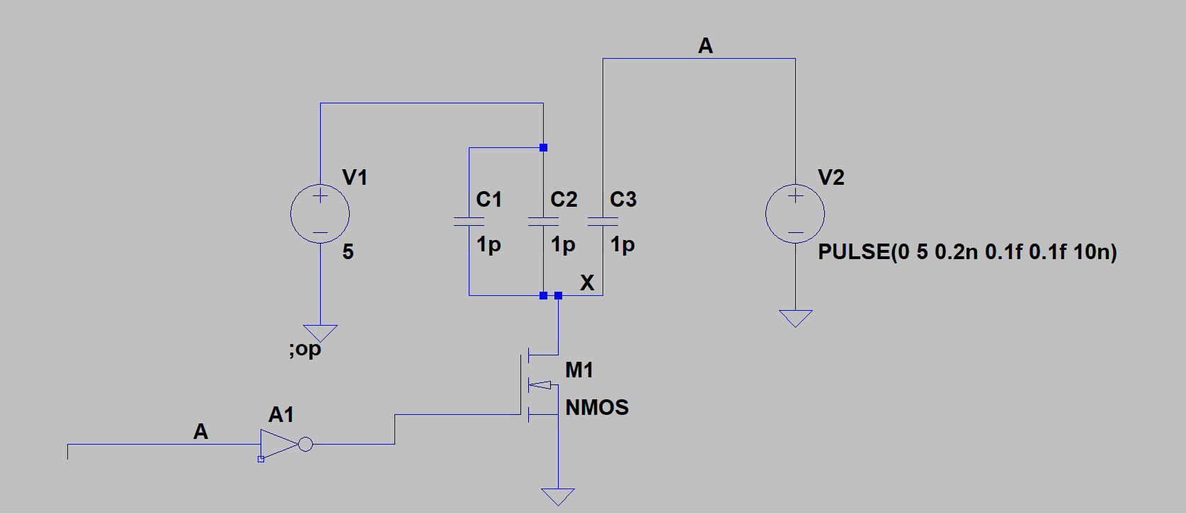
I am unable to understand how the voltage at Node x in the below circuit is 5V/3 once A rises and M1 NMOS turns off.

enter image description here

So A is initially 0 and once A rises to 5 V, the NMOS turns off.

Since NODE X is floating, I think the node X should be 5V, however simulation shows it's 1.66.

Could anyone help me figure this out?

\$\endgroup\$
1
  • \$\begingroup\$ C{1,2,3} form a capacitive divider. For node X to return to 5V you also have to charge/discharge C1&2. \$\endgroup\$
    – sstobbe
    Commented Sep 24, 2017 at 0:54

1 Answer 1

0
\$\begingroup\$

Since you're doing a DC operating point analysis from the perspective of the DC signal, the pulse source is a ground since alternating sources act as short circuits. If you add C1 and C2 together, you can simplify the circuit to just a 5V DC source connected across two capacitors: C12 = 2pF and C3 = 1pF.

For capacitors in series, each capacitor has the same charge on it. Therefore Q12 = Q3 = Q. If we further reduce the series capacitors C12 and C3 to

Ct = = (1/C12 + 1/C3)^-1 = (1/2pF + 1/1pF)^-1 = 2/3pF,

we know this simplified capacitor has a voltage of 5V and a charge of 2Q, since charges in series add. So, since CV=Q:

2/3pF * 5V = 2Q -> Q = 1.6667 pC

Now, if we go back to the C12 and C3 combination, Q is the charge across C3. And again from CV=Q, we have:

C3 * V = Q -> V = 1.6667pC/1pF = 1.6667 V

or V = 5/3V

\$\endgroup\$
5
  • \$\begingroup\$ When node x = 1.67V the voltage across C3 is 3.33V, the charges are equal not additive. V(x) = 5 - 3.33pC/1pF I believe \$\endgroup\$
    – sstobbe
    Commented Sep 24, 2017 at 2:20
  • \$\begingroup\$ Since the charge across C12 and C3 are equal, the charge across both of them is the sum of them. Q12=Q3=Q, which is why the charge across both C12 and C3 is 2Q. And are you talking about the DC voltage? If the DC voltage at X is 1.67V, then the voltage across C3 would also be 1.67V since the pulse source acts as a short circuit, i.e. ground. \$\endgroup\$
    – royalt213
    Commented Sep 24, 2017 at 2:24
  • \$\begingroup\$ If the pulse acts as short in DC op, then the voltage at node x should be the voltage across C3, which should be twice of voltage across C1 and C2, so 3.33 V. However if I run a transient then voltage at node X is 1.67 V. \$\endgroup\$
    – Ash
    Commented Sep 24, 2017 at 5:04
  • \$\begingroup\$ How did you get that? I've looked at my analysis a few times and can't see anything wrong with it. Where are you getting 3.33V and why should the voltage across C3 be twice that of C1 and C2? \$\endgroup\$
    – royalt213
    Commented Sep 24, 2017 at 6:03
  • \$\begingroup\$ "We know this simplified capacitor has a voltage of 5V and a charge of 2Q, since charges in series add" The equivalent cap will have charge Q on it not 2Q. Think of charge as current flowing through circuit, the equivalent Cap will also have charge Q. \$\endgroup\$
    – Ash
    Commented Sep 25, 2017 at 19:31

Your Answer

By clicking “Post Your Answer”, you agree to our terms of service and acknowledge you have read our privacy policy.

Not the answer you're looking for? Browse other questions tagged or ask your own question.