7
\$\begingroup\$

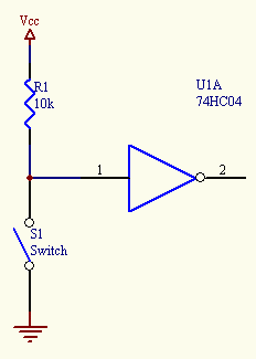
enter image description here

Let's say 1 is an input pin.

So when the switch is "OFF" (open circuit), the output is almost equal to Vcc since there's no current. 1 is pulled to Vcc.

When the switch is "ON" (closed circuit), 1 is pulled to the ground and there's a current between Vcc and the ground. But why 1 is not pulled to Vcc when the circuit is closed? Assuming Vcc is 5V, how much voltage goes to 1 when the circuit is closed?

If 1 is pulled to ground when the circuit is closed, does it mean that the ground has higher voltage than Vcc in this case?

UPDATE:
All answers are appreciated and all of them helped. Thanks a lot for the effort.

\$\endgroup\$
7
  • 6
    \$\begingroup\$ you're confusing voltage and current. Voltage doesn't "go" anywhere. When the switch is closed, the node at 1 is pulled to GND, and there's simply no physical way that would not be the case. So, frankly, I don't understand the question: When you define Vcc to be 5V above GND, then you defined GND to be lower voltage than Vcc. Asking whether the opposite is the case makes no sense at all. \$\endgroup\$ Commented Nov 11, 2017 at 15:48
  • \$\begingroup\$ @MarcusMüller, I thought that "HIGH" input means 5V in this case and "LOW" means voltage equal to "GND". When the circuit is closed, why the input is "LOW" and not "HIGH"? \$\endgroup\$ Commented Nov 11, 2017 at 15:55
  • 2
    \$\begingroup\$ When you close the switch, it is a very low-impedance connection to GND. Replace S1 with a 1R resistor and solve for the voltage at the input of the inverter. \$\endgroup\$
    – M D
    Commented Nov 11, 2017 at 15:56
  • 2
    \$\begingroup\$ @user1764381 no, HIGH and LOW are about voltage. To work out the voltage, you can use the current. \$\endgroup\$
    – BeB00
    Commented Nov 11, 2017 at 16:00
  • 1
    \$\begingroup\$ Not going to get into this, but for this CMOS device, it really is more about the voltage than the nanoamp current leakage edit: also, your answer is clearly overcomplicating the OP's simple question \$\endgroup\$
    – BeB00
    Commented Nov 11, 2017 at 17:37

4 Answers 4

10
\$\begingroup\$

Actually, to confuse you more..

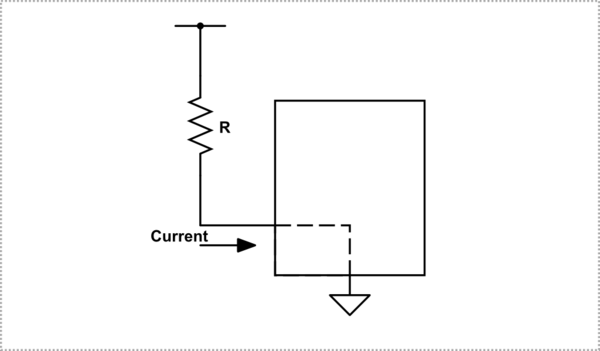
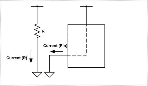
One, is current going into the pin, and Zero is current coming out of the pin. For one you have to supply the correct current to maintain the input at a high enough voltage. For a low you have to extract enough current to keep the input voltage low enough.

When the switch is open, a small current flows into pin 1 and eventually ends at ground through the device. If the resistor is not too large, the voltage drop across the resistor will be small and the voltage at the pin will be near Vcc, or more accurately, high enough above the high level logic threshold.

schematic

simulate this circuit – Schematic created using CircuitLab

When the switch is closed, obviously current is flowing through the resistor to ground, but there is another simultaneous current path from Vcc through the device, out the pin, through the switch to ground. Since, with a switch, the pin is hard connected to ground, the voltage at the pin will be zero volts with respect to that ground.

schematic

simulate this circuit

Notice when the switch is closed the resistor does nothing useful for the power it is dissipating.

For a standard (non CMOS) TTL device the zero logic level current coming out of the pin is MUCH larger than the high level current that enters the pin. For CMOS parts the high level and low level currents are almost equivalent and very small since all they do is maintain the charge, or lack of charge, on the input capacitance of the device.

\$\endgroup\$
4
  • \$\begingroup\$ Thanks @Trevor. obviously current is flowing through the resistor to ground, do you mean that when the switch is closed, no current is flowing through R1 to the input pin? \$\endgroup\$ Commented Nov 11, 2017 at 16:14
  • 1
    \$\begingroup\$ @user1764381 that is correct. When the switch is closed you effectively have two circuits. One is the resistor. \$\endgroup\$
    – Trevor_G
    Commented Nov 11, 2017 at 16:16
  • \$\begingroup\$ @Trevor - Hi, regarding "For a TTL device, as you have shown, the zero logic level current coming out of the pin is MUCH larger than the high level current that enters the pin." - But the OP has shown a 74HC04, so not TTL (that's CMOS fab, with CMOS logic thresholds, in a TTL-compatible pinout) and it doesn't have the TTL input current behaviour that you mention. Therefore perhaps better not to get into the TTL behaviour except as a side-note? Or did I miss something? \$\endgroup\$
    – SamGibson
    Commented Nov 11, 2017 at 16:30
  • 1
    \$\begingroup\$ @SamGibson Thanks, you are of course correct, I must admit I only glanced at the OP's image. Fixed :) \$\endgroup\$
    – Trevor_G
    Commented Nov 11, 2017 at 16:31
10
\$\begingroup\$

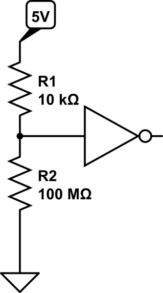
As @MD says, you can think of it like a potential divider:

When the switch is off, the resistance of the switch will be very high (probably much larger than 100Mohm).

schematic

simulate this circuit – Schematic created using CircuitLab

If we use the divider equation, we can find the voltage at the input to the inverter:

V=Vin*(R2)/(R1+R2)=5*100,000,000/(10,000+100,000,000)=4.9995V, which is basically 5V.

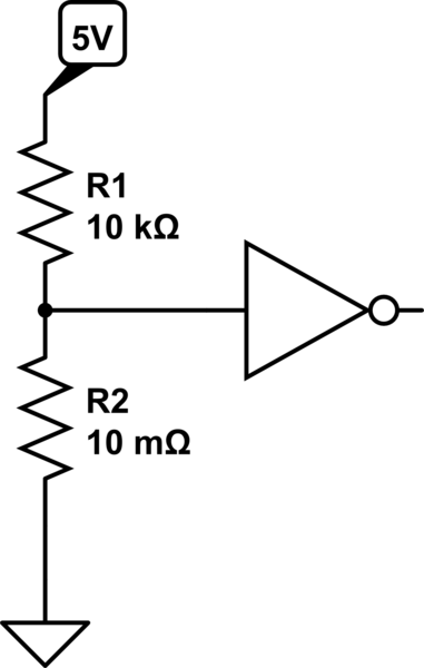
When the switch is closed:

schematic

simulate this circuit

We can again use the divider formula: V=Vin*(R2)/(R1+R2)=5*0.01/(10,000+0.01)=0.00000499V, which is basically 0V.

\$\endgroup\$
6
\$\begingroup\$

But why 1 is not pulled to Vcc when the circuit is closed?

If you like, consider the closed switch is a resistor with a very low value, probably 1 ohm or lower. You can look in the datasheet to get the maximum resistance for the switch you actually plan to use in your circuit.

Now you have a voltage divider, and

$$V_1 = V_{cc}\frac{R_{sw}}{R_{sw}+R_1}$$

Since \$R_{sw}\$ is (we're assuming) about 1 ohm and \$R_1\$ is 10 kilohms, if \$V_{cc}\$ is 5 V we get about 0.5 mV at 1, which is well below the the threshold for a logical low.

\$\endgroup\$
2
\$\begingroup\$

For an intuitive understanding, it might be useful to pull out the old water pipe analogy. So let's replace the electricity in your circuit with water:

Your wires are now hoses that the water flows through. Vcc is a tap connected to your house plumbing. Ground is a drain.

The resistor is a coil of really narrow tubing that only lets the water slowly trickle through. The switch is a valve that you can open or close. The NOT gate, which basically acts as a voltage sensor, is now a water pressure gauge.

The important part to remember about the water analogy is this: Current is flow. Voltage is pressure.


Now, let's first see what happens when we open the tap and close the valve. Of course, the water from the tap will flow into the hose until it reaches the narrow tubing. The tubing will slow down the water flow, and cause pressure to build up in the hose feeding into it, but some water will still slowly trickle through. This trickle of water will next reach the drain valve (and the pressure gauge, which is connected to the same hose), but since the valve is closed, it cannot get any further.

So the pressure in the hose between the tubing and the valve will slowly build up, until it becomes equal to the pressure on the other side of the tubing (and to the pressure in the water mains feeding the tap). At that point, all the water will be at the same pressure, there will be no more flow, and the pressure gauge will register a high pressure equal to that inside your house plumbing.


Next, let's open the drain valve. Now all the water in the hose between the tubing and the valve can flow out, and the pressure will drop.

The water in the hose between the tap and the tubing will still be at high pressure, though, and so will start to flow out through the tubing. But since the tubing is narrow, the water can't flow through it very fast, and only a trickle of water will come out.

And that trickling water will immediately flow out through the open valve and down the drain, as fast as it comes out of the tubing. Thus, despite the trickle of water coming out of the tubing, the pressure gauge will read approximately zero.

\$\endgroup\$

Not the answer you're looking for? Browse other questions tagged or ask your own question.