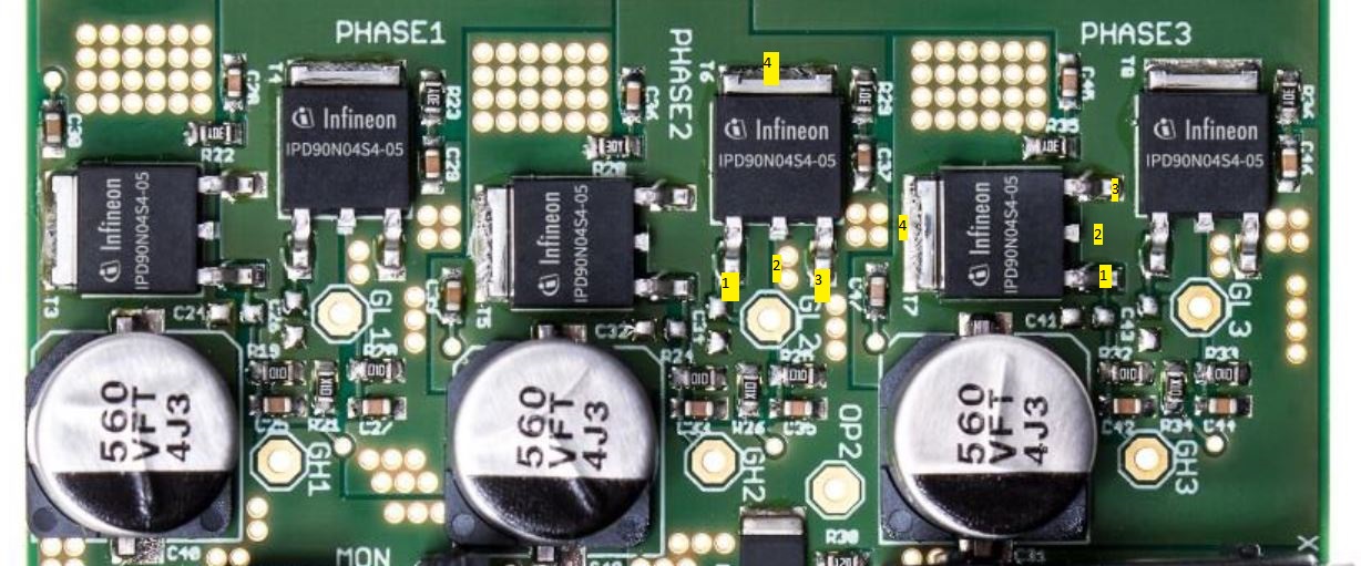
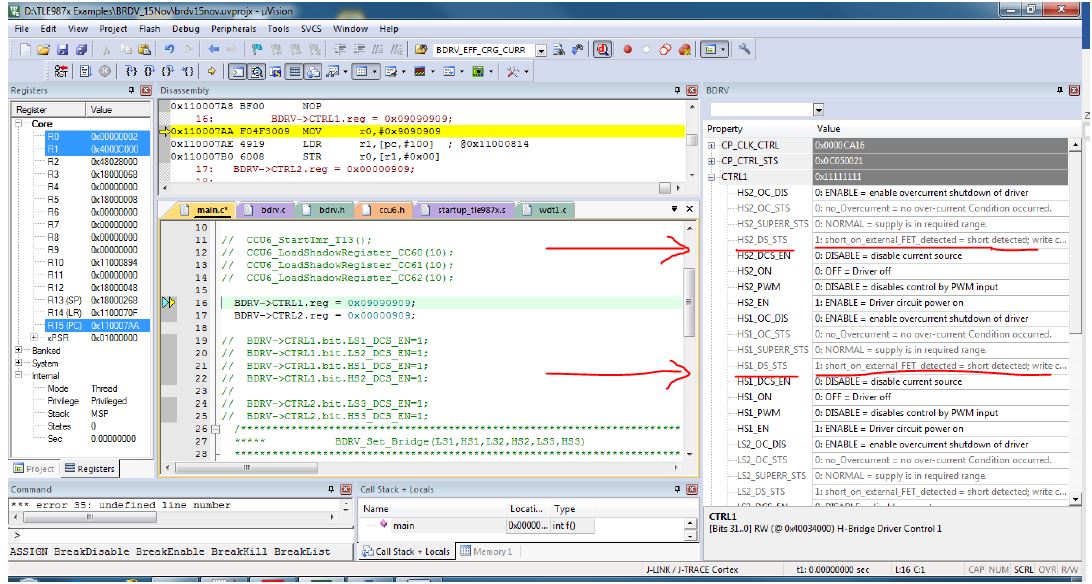
I have been stuck with this problem for last one month unable to figure out whether it is a software problem or hardware problem.
I don't have your hardware in front of me. However, based on the information you have given, and my own research, I'll give you my hypothesis. I would start by suspecting software, not a genuine hardware fault, for the following reasons:
a) If the interpretation of a FET source-drain short was valid, as per your interpretation, for all 6 MOSFETs, then you would have needed to damage them all, at the same time.
Damaging 6 Power MOSFETs so that they are shorted would, in my experience, usually have been obvious (noise, smell, smoke, damage to the device package etc.).
b) The chances of all 6 Power MOSFETs being damaged (as per your interpretation) is not very likely (if it was just one or two damaged devices being reported, that would be different).
c) As you have said, you can't actually measure a source-drain short, again suggesting that this is a false report.
d) In your question's title, you asked for the reason for "MOSFET over current". However the status bits which are set at that point in your code, are not for overcurrent. Notice that the status bits which are set in register CTRL1, are the HSx_DS_STS bits not the HSx_OC_STS bits, so the detection mechanism is different. It seems that you are trying to perform a Bridge Driver "Off-Diagnosis".
e) Possible error in the TLE987xQX User Manual linked from this page.
In section 27.4.1.1.1 ("Preparation") notice how figures 218+219 and 221+222 are identical, yet the text before each of those saying which bits should be set in each figure, are not identical. Therefore either the figures or the text are wrong, IMHO. I suspect figures 218+219 are wrong, as the text does not match those.
Step A in that Bridge Driver "Off-Diagnosis" procedure says:
A: All phases must be switched in "Enabled"-state (but not "ON"-state)
However figures 218+219 (wrongly?) highlight the DCS_EN bits not the EN bits in the CTRL1 and CTRL2 registers! So the figures do not match the text.
After step A, you have to do step B, involving writing to CTRL3. Then the DCS_EN bits should be set later, in step C:
C: Enable Drain-Source Current Sources on the High-Side (HSx) drivers
And only after that, you perform step D, clear the DS_STS flags, and check whether they remain clear:
D: Assuming the motor contacts do not have a short to VBAT or to GND, all the DS-Status flags of each phase can be cleared now, and shall stay cleared.
Therefore I suspect you are being misled about the correct software procedure, due to the contents of figures 218+219 which suggest you set the DCS_EN bits at step A (which we can see you doing, where you write 0x09090909 to CTRL1, for example). However the User Manual says those bits are set at step C.
f) There is the possibility of a motor problem, causing all HSx_DS_STS or all LSx_DS_STS bits to be set, as explained in section 27.4.1.1.2 (Detection).
However since you are reporting all HSx_DS_STS and all LSx_DS_STS bits to be set, then this possibility doesn't make sense. You could investigate running the same test with the motor disconnected. Obviously the "open load" would be reported, but if the DS_STS bits are still set, then a disconnected motor can't cause that!
g) I had a quick look at some sample code from the Infineon site, but (i) I couldn't see any sample code which included that Bridge Driver "Off-Diagnosis" which you are attempting, so I couldn't see what they demonstrate as the correct procedure, and (ii) their download licensing would prevent me showing it to you anyway, as the license prohibits public disclosure of code from a download. :-(
h) At the point in your code that you show in the screenshot (and you might not even be allowed to show that, based on the download license that I saw!) it seems you might be looking at the CTRL1 status bits after just step A in the procedure. That would be incorrect - you need to perform the other steps before then clearing the DS_STS bits and seeing if they remain clear.
As it says after step A in the User Manual:
The DS-Status Flags are still set in this state of the Bridge Driver, but since the Drain-Source-Current Sources are not enabled these flags do not have a meaning yet.
So before you follow the other steps, including enabling the current sources later, then seeing the DS_STS bits "set" has no meaning at that point. It seems that you might be making that mistake in the interpretation of those bits (but I can't be sure, based on only that small amount of code visible in the screenshot).
I hope that gives you some ideas. As I said at the start, this is just a hypothesis, which I can't test without the hardware.
If possible, try to go back to a version of your code which you know was working, on a date before the first date you believe things "went wrong" (I hope you have some kind of SCM system e.g. Git, SVN etc.).
When the website became viewable again today, I noticed that you weren't getting any replies on the Infineon forums. I suggest you could also contact Infineon support directly through their "Technical Assistance Center (TAC)" if you need more help, or via whichever distributor you are using. Good luck!


