1
\$\begingroup\$

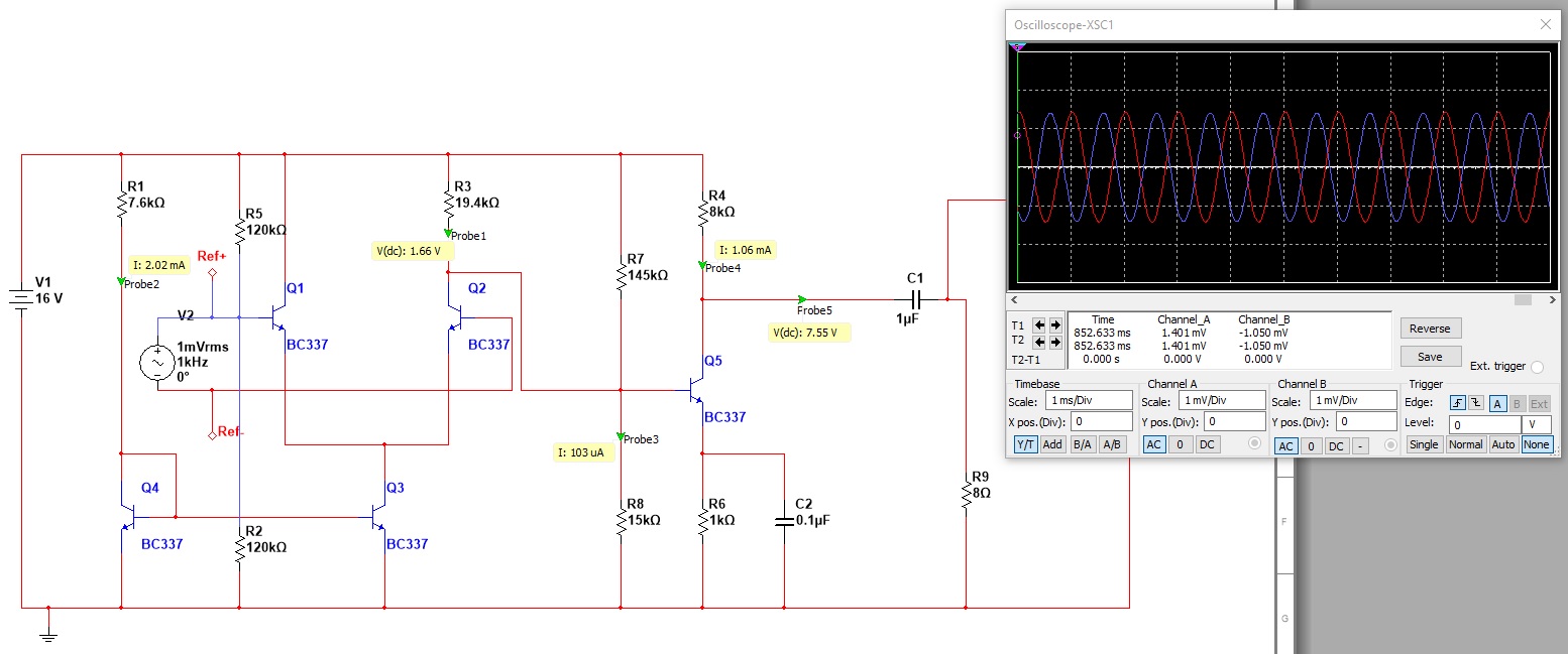
I am having difficulty understanding why I am getting unity gain from the circuit below. Before I added the common emitter stage, there was a gain of around 150, and I wanted to add another 10 X gain to that, but as soon as the CE part was connected that gain went to around -1.

Looking at the probes, it seems to me that everything is in order: 1/10th current at CE transistor base, mid point DC bias at output.. shouldn't the ratio of collector and emitter resistors give at least 8 X gain?

I've studied separate components of these amplifiers in textbook format, but getting stages to work together in a practical application is, unfortunately, beyond me for now.

Why?

Thanks for any help you can give.

\$\endgroup\$
1
  • \$\begingroup\$ Is your tail current (set thru R1) too high? \$\endgroup\$ Commented Dec 19, 2017 at 17:20

1 Answer 1

1
\$\begingroup\$

Your bias network is being upset by the DC coupling to R3 — note that R3 and R7 are connected directly in parallel. You need a blocking capacitor there.

Or else arrange the biasing of the differential stage so that you don't need to bias the next stage separately.

\$\endgroup\$
2
  • \$\begingroup\$ Thanks Dave, I hadn't actually realised they were in parallel! I set up the quiescent voltage of around 1.66 at the output of the differential pair on purpose so as to just bias Q5 and try to get more gain from the collector and emitter resistor ratios. Will it be possible to get 1500+ voltage gain from this circuit providing I bias it correctly? \$\endgroup\$
    – Yossarian
    Commented Dec 19, 2017 at 15:10
  • \$\begingroup\$ I am no expert but I have seen a similar circuit where they use a PNP transistor with BE (plus resistor? can't remember) over R3. \$\endgroup\$
    – Oldfart
    Commented Dec 19, 2017 at 15:14

Your Answer

By clicking “Post Your Answer”, you agree to our terms of service and acknowledge you have read our privacy policy.

Not the answer you're looking for? Browse other questions tagged or ask your own question.