3
\$\begingroup\$

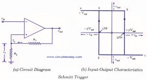
The Opamp inverting schmitt trigger is constructed as shown.

An inverting schmitt trigger

The output signal is:

The Output Signal of an inverting schmitt trigger

So I ask why is the output at the start of operation saturated to positive?

Also, if the input voltage is moved from the negative to positive terminal the starting output will saturate to negative. Why?

Is there a rule to follow? If so, what causes this rule?

What will happen if R1 is replaced with a capacitor, as in a monostable multivibrator? What will be its starting saturation level that will charge the capacitor. What will be the UTP and LTP then?

\$\endgroup\$
8
  • \$\begingroup\$ There seems to be a legitimate question in there, but there writing is incomprehensible. Closing until we get something written in English. \$\endgroup\$ Commented Jan 9, 2018 at 11:56
  • \$\begingroup\$ Sorry about that, but the question is quite fuzzy by nature. What determines the saturation level of a Schmitt Trigger at the beginning of its operation when the input is between UTP and LTP \$\endgroup\$ Commented Jan 9, 2018 at 13:00
  • \$\begingroup\$ @RaafatAbualazm, see the comment in my answer \$\endgroup\$
    – MCG
    Commented Jan 9, 2018 at 13:05
  • \$\begingroup\$ One question per question, please! If the input is moved to positive terminal or R1 is replaced by a cap, it will not be a Schmitt trigger anymore. \$\endgroup\$ Commented Jan 9, 2018 at 14:18
  • \$\begingroup\$ Oh sorry! But I have a test tomorrow and the professor and the section guy don't understand the circuit. \$\endgroup\$ Commented Jan 9, 2018 at 14:43

3 Answers 3

3
\$\begingroup\$

The Schmitt trigger works similar to a comparator, so imagine you have a comparator with a Vref in the non inverting input. When the input voltage falls below that threshold, the output of the comparator saturates high. If the input voltage then goes above the threshold, the output goes low. If you were to put the Vref into the non inverting input, the same rule applies, but backwards, so when the input goes below the threshold, the output goes low, and if it then goes above, the output goes high.

The general rule is if the non inverting input is less than the inverting input, the output will be high.

The Schmitt trigger works in almost the same way, except it has upper and lower limits. As you can see from your diagram, the input voltage (sine wave) starts at 0, which means the inverting input is lower than the non inverting, hence the output starts high. Once it goes above the high threshold, the output goes low. With a Schmitt trigger, the output will stay low untill the lower threshold is met.

As with the comparator, if you were to swap the input voltage to the non inverting input, it would be the other way round.

I believe this is what you were asking, but please correct me if I am wrong as the English was rather poor, as Olin pointed out.
\$\endgroup\$
13
  • \$\begingroup\$ Well we have two refrences, the postive and tge negative. \$\endgroup\$ Commented Jan 9, 2018 at 12:54
  • \$\begingroup\$ Why should yhen we start with the positive reference? May be 0 is less than the positive one, but it might have been a negative reference in the beginning. If 0 is more than the negative level then it should saturate at the negative level. \$\endgroup\$ Commented Jan 9, 2018 at 12:58
  • \$\begingroup\$ Yes, that is how the Schmitt trigger works. Look at the output compared to the input sine wave. It works the same as I describes, when the input goes above the upper threshold, the output swings low, and when it is below the lower threshold, the output swings high \$\endgroup\$
    – MCG
    Commented Jan 9, 2018 at 13:02
  • \$\begingroup\$ You don't have 2 'references', you have a high and low threshold. As for why the output starts high when the input starts in between the 2 threshold levels, that is just for ease of showing how the circuit works. It's not an oscilloscope screenshot. They have to show the operation of a circuit, and when doing this, a sine wave will usually start at 0. As it is below the upper threshold, it would not make sense to have it 'indetermined' in a circuit example, so they show it high (as it would normally be at that point mid operation). \$\endgroup\$
    – MCG
    Commented Jan 9, 2018 at 13:05
  • \$\begingroup\$ I am asking about the beginning of the operation , at t = 0 and the input is between UTP and LTP what should be my reference? Positive or negative saturation level. \$\endgroup\$ Commented Jan 9, 2018 at 13:05
3
\$\begingroup\$

How to determine the saturation level when an opamp schmitt trigger starts workig?

With the "theoretical" circuit you have shown and the input at 0 volts, upon power being applied, there is no real way to determine what the output state will be. The output anomaly will resolve itself when the input signal passes one of the two thresholds. Once this has resolved, the output is unambiguous.

Many applications will want the output to be unambiguous at power-up (in the absense of a significant input signal) and circuit measures can be taken to force a high or low situation at the output but, on a simple theoretical circuit like the one shown, it is impossible to determine.

\$\endgroup\$
7
  • \$\begingroup\$ Then how to force it to become undeterminate? \$\endgroup\$ Commented Jan 9, 2018 at 12:58
  • \$\begingroup\$ If you want to force it to be indetermined, keep it below the thresholds \$\endgroup\$
    – MCG
    Commented Jan 9, 2018 at 13:01
  • \$\begingroup\$ @RaafatAbualazm I'm not sure your original comment made sense - forcing something to be undeterminate doesn't mean anything sensible. Forcing something to be determinate does. As MCG comments, keep it below the thresholds continues keeping it undeterminate but I don't think this is what you are asking about. I think you are asking how to make the output unambiguously high or low at power-up. To do this you can use a capacitor to the negative rail from the non-inverting input to keep the output low or, a cap from pos rail to keep the output high at power-up. \$\endgroup\$
    – Andy aka
    Commented Jan 9, 2018 at 13:16
  • \$\begingroup\$ That I meant. Sorry, I'm having hard times these days. But what happens if I replace a resistor with a capacitor in the postive feedback loop. \$\endgroup\$ Commented Jan 9, 2018 at 13:20
  • \$\begingroup\$ Oh.... yeah sorry, I must have read that differently! \$\endgroup\$
    – MCG
    Commented Jan 9, 2018 at 13:42
2
\$\begingroup\$

For the sake of theory, we assume an initial state of output.

Here in your circuit for inverting schmitt trigger, it is assumed to be \$+V_{sat}.R_2/(R_1+R_2)\$ at the non-inverting terminal, at t= 0, and the circuit waveforms are analysed.

Even if you assume it to be \$-V_{sat}.R_2/(R_1+R_2)\$ at t =0, you will eventually end up in the same waveform, as the outputs are resolved itself. The same happens in real circuits too.

\$\endgroup\$
6
  • \$\begingroup\$ How is the output to resolve , please? \$\endgroup\$ Commented Jan 9, 2018 at 13:17
  • \$\begingroup\$ Instead of +Vsat, assume -Vsat at Vo for t= 0. It will still resolve automatically to the required waveform of the figure. You can draw the corresponding waveforms and prove it yourself. \$\endgroup\$
    – Mitu Raj
    Commented Jan 9, 2018 at 13:20
  • \$\begingroup\$ So the point is...initial state you can assume of your choice. \$\endgroup\$
    – Mitu Raj
    Commented Jan 9, 2018 at 13:33
  • \$\begingroup\$ It doesn't really matter \$\endgroup\$
    – Mitu Raj
    Commented Jan 9, 2018 at 13:37
  • 1
    \$\begingroup\$ It will resolve but after a cycle or so. Not instantly, I thought It'd be in an instant \$\endgroup\$ Commented Jan 9, 2018 at 13:53

Your Answer

By clicking “Post Your Answer”, you agree to our terms of service and acknowledge you have read our privacy policy.

Not the answer you're looking for? Browse other questions tagged or ask your own question.