10
\$\begingroup\$

I'm looking for an analog method of measuring the phase difference between two signals operating at frequencies in the range from (0 - 20 MHz). I'm wondering if there's an IC that does that or a specific circuit that converts the phase difference into a voltage signal.

Thank you very much

\$\endgroup\$
5
  • \$\begingroup\$ Didn't you want to measure the phase of analog signals? \$\endgroup\$
    – stevenvh
    Commented Jul 10, 2012 at 13:23
  • \$\begingroup\$ Yes, which is achieved by the selected answer. Unless I misunderstood something \$\endgroup\$
    – alqubaisi
    Commented Jul 10, 2012 at 17:15
  • 1
    \$\begingroup\$ I've never used the 4046, but if I look at the signal input I only see digital functions: an XOR port and a Set-Reset flip-flop. Also the comparator input is derived from a binary divider. IMO it's a digital device. \$\endgroup\$
    – stevenvh
    Commented Jul 10, 2012 at 17:18
  • \$\begingroup\$ Do you know of any analog solution ? Something that would produce a DC output as a function of phase difference ? Thanks \$\endgroup\$
    – alqubaisi
    Commented Jul 10, 2012 at 17:32
  • \$\begingroup\$ I assume that your signals are sines, otherwise the word phase is meaningless. In my answer I subtract two sines, and the difference between two sines is always a third sine, whose amplitude is proportional to the phase difference. \$\endgroup\$
    – stevenvh
    Commented Jul 10, 2012 at 17:50

3 Answers 3

5
\$\begingroup\$

With more specifics on input and output Voltage range, a better answer can be provided.

To measure phase, as Steven says assuming they are equal amplitude and linearity you can subtract but this is a time-variant signal not DC phase output, so one might use a Peak Detector to rectify that signal to mix the result to generate a DC voltage for Phase difference.

The amplitude needs to be normalized (the same) so linear slicers or limiters are used as well as XOR gates ( which is a logic gate that also works here as a mixer/phase detector for logic level signals.

THere are many other ways too such as edge detect, S&H sawtooth clock and Time Interval counters.

.. A better way that I suggest is the 4046 PLL chip.

Do you want 0~180 deg = 0 to Vdd? then use TYPE I "XOR gate" chip or 0~360 deg then use the Type II edge detect phase detector.

CMOS 4046 PLL chip is very easy to use, and has been around since mid 70's, when I first used it.
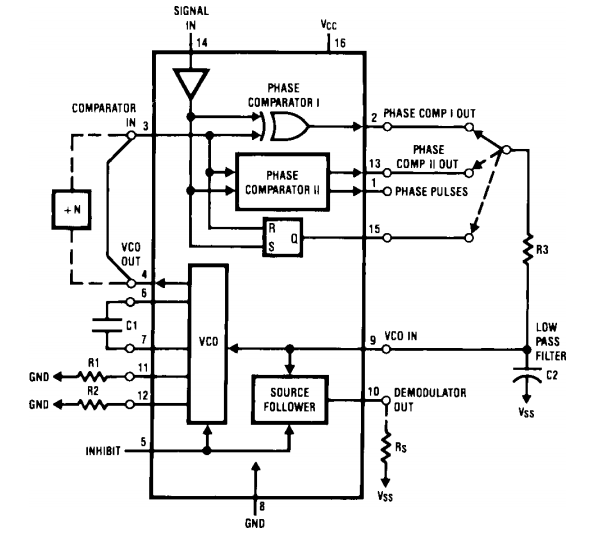
enter image description here

\$\endgroup\$
2
  • \$\begingroup\$ Good idea. The pinout of the 4046 lends itself to opening the feedback loop from the PC to the VCO, leaving the PC output to provide a measure of the phase shift. 3 PCs to choose from - which provides flexibility - but which one? TI seems to be the only mfr still producing this part, but one needs to be aware that there are still spec sheets floating around for the older CD4046 parts. There are substantial diffs between these parts and the newer HC4046 parts. There's also a new-ish 9046 from Philips/Nexperia. \$\endgroup\$
    – Seamus
    Commented Nov 3, 2020 at 6:50
  • \$\begingroup\$ @seamus It depends on your specs for frequency error % between VCO out and f input and choice of BW of LPF to permit capture. The 9046 has improved VCO error of 10%. Choose Type II for any frequency error within range of VCO as this is phase and frequency detector but more jitter since it uses edge detectors rather than type I state or binary level XOR mixer. This inherently a frequency doubler,just like a diode bridge. \$\endgroup\$
    – D.A.S.
    Commented Nov 3, 2020 at 9:59
11
\$\begingroup\$

Solution for analog signals:

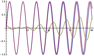
if you simply subtract both signals you get a signal whose amplitude will increase with increasing phase difference:

enter image description here

As the purple signal's phase shifts the difference signal's amplitude increases. The error signal is zero when both signals are in phase (at t = 5).

enter image description here

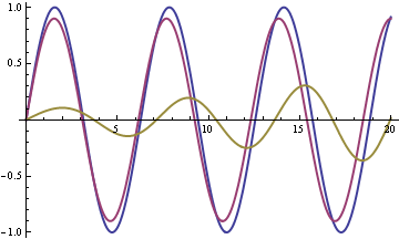
Here both signals start out at the same phase, and the difference signal is only caused by the difference in amplitude. So you'll have an offset if both signals don't have the same amplitude. If \$P\$ = \$A\$ - \$B\$ then applying an envelope detector (peak detector) to all three signals gives you \$Phase\$ = \$A_p\$ - \$B_p\$- \$P_p\$.

\$\endgroup\$
3
\$\begingroup\$

Another chip is the AD8302, which gives you an analog signal proportional to phase difference, and another proportional to log(amplitude ratio). It's kind of expensive, but it works up to a couple GHz; see http://www.analog.com/en/rfif-components/detectors/ad8302/products/product.html

(Disclaimer: haven't actually used it myself)

\$\endgroup\$

Your Answer

By clicking “Post Your Answer”, you agree to our terms of service and acknowledge you have read our privacy policy.

Not the answer you're looking for? Browse other questions tagged or ask your own question.