0
\$\begingroup\$

I have a question related to the amplifier circuit given in datasheet of 2SC1946A The circuit looks like this: enter image description here
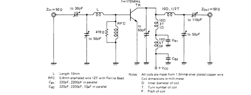
I need some info on the inductors used in the circuit. Following are my questions:

  1. What is the value of inductor L? Nothing is mentioned about L except L: Length 10mm. What does it mean?
  2. What is 1D (if D stands for Diameter)? Is it 1 mm diameter? Is it practical to wind a coil of 1 mm diameter with 1.5mm wire?
  3. How to wind 1/2 Turn of a coil? How should it look like?
  4. What is pitch of a coil. Is the gap between 2 parallel lines of winding wires?
  5. Should I change any component in this RF amplifier circuit if the input signal's frequency changes? Which Inductor and Capacitor duo forms the tank in this circuit, which is responsible for 150 MHz frequency?
\$\endgroup\$
3
  • \$\begingroup\$ It tells you that in the "Notes". (though I suspect "1D" in the collector circuit should be "1P" to match the other similar inductor) \$\endgroup\$
    – user16324
    Commented Feb 23, 2018 at 22:06
  • 1
    \$\begingroup\$ Wow... this circuit diagram is evil. One of the inductors has "10D" and "1D" - I assume the "1D" should be "1P"... I think L is just a length of straight wire, but it's not exactly obvious... Well, at least I can answer #2 - all the coils are 10mm diameter. \$\endgroup\$
    – Selvek
    Commented Feb 23, 2018 at 22:14
  • \$\begingroup\$ @Selvek is right, an evil circuit. Inductor L is just a straight wire, but its proximity to ground isn't mentioned. And the ferrite of the ferrite bead is not specified. Even if you build all the inductors exactly as described, the parts layout will influence circuit operation (no photo was included). I'd treat this circuit as an example power amplifier. It might serve as a starting-point, but you should understand the purpose of each component before trying to duplicate it (your questions suggest you have insufficient knowledge). \$\endgroup\$
    – glen_geek
    Commented Feb 23, 2018 at 22:29

1 Answer 1

1
\$\begingroup\$

This part is ca.'97 and notation is limited to length, diameter, turns and pitch for higher SRF.

Quite often big loops used coax from centre to shield. Orientation must be orthogonal unless far enough away to prevent mutual coupling in many cases.

In short there is insufficient info for you to build this and you would need all the RF test equipment to tune it with 5 variable caps and know what to look for. The silver 1.5mm wire has high Q due to skin effects.

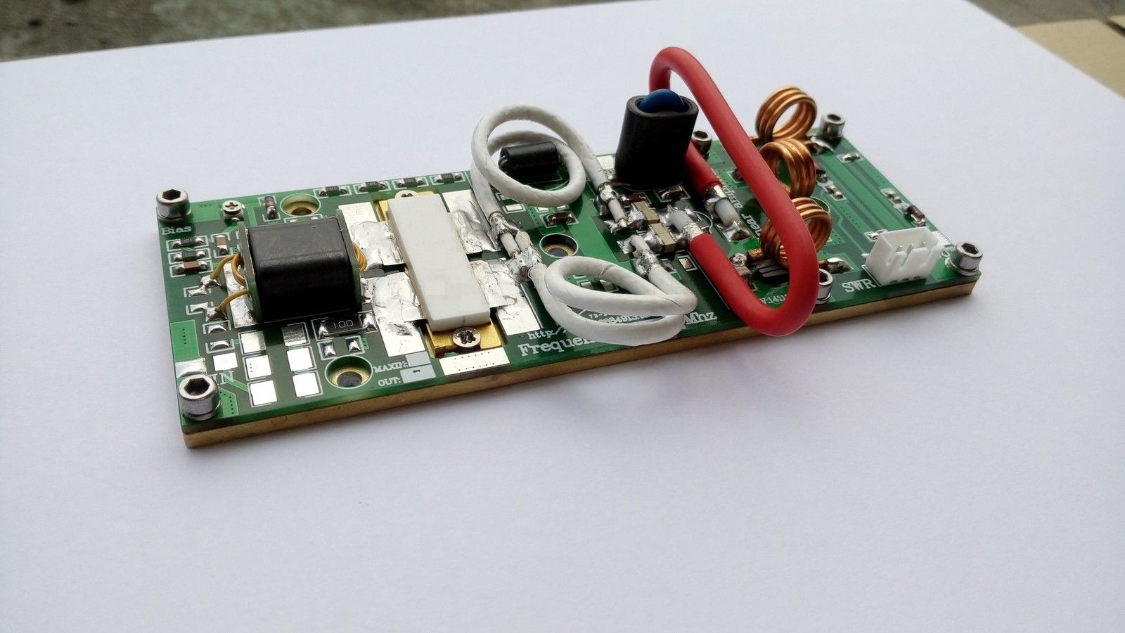
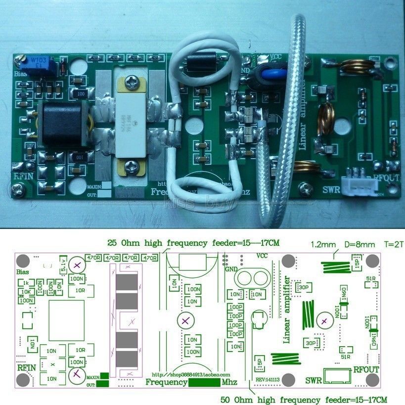
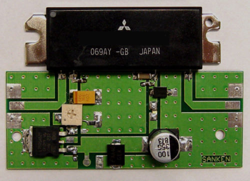
Here are some ideas of various implementations :

100W 80~170MHz FM with SWR portenter image description here

Ham Tx Kit. 100W 80~170MHz enter image description here

40W 170~225MHz

Suggestion

buy a kit. or tested board ~$2/W

\$\endgroup\$

Your Answer

By clicking “Post Your Answer”, you agree to our terms of service and acknowledge you have read our privacy policy.

Not the answer you're looking for? Browse other questions tagged or ask your own question.